Overview
The Power Plant Parameters panel is organized into five tabs:- System Technology and Capacity Targets — Select the inverter and module, define capacity targets (MWdc, MWac), set the desired DC:AC ratio, and choose how DC blocks are rendered on the map.
- DC Design — Configure mounting type, tracking method, table geometry, and row spacing parameters.
- AC Design — Define inverter setpoints, transformer settings, and electrical losses.
- Losses — Specify DC loss factors and thermal model parameters.
- Slope Design — Choose between Simplified or Advanced Plant Layout modes with terrain and shading options.
User Inputs
System Technology and Capacity Targets
Configure the core system components and capacity targets that define the overall power plant design.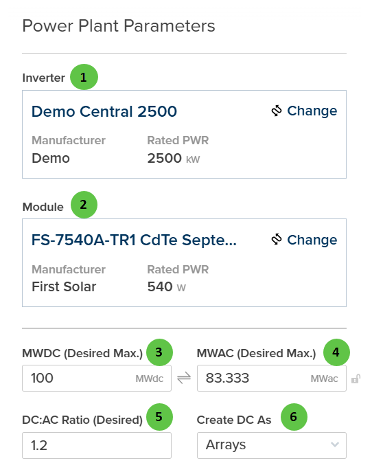
| # | Input | Type | Units | Description | Related Documentation |
|---|---|---|---|---|---|
| 1 | Inverter | Selection Panel | — | Displays the currently selected inverter with Manufacturer and Rated Power (kW). Click Change to open the inverter selection dialog and choose a different inverter model from the library. | Inverter Library, Inverter |
| 2 | Module | Selection Panel | — | Displays the currently selected PV module with Manufacturer and Rated Power (W). Click Change to open the module selection dialog and choose a different module from the library. | Module Library, Table |
| 3 | MWDC (Desired Max.) | Text Field | MWdc | Target maximum DC capacity for the power plant. The automated layout engine will attempt to place DC blocks until this capacity is reached or the available site area is filled. | — |
| 4 | MWAC (Desired Max.) | Text Field | MWac | Target maximum AC capacity for the power plant. Linked to MWDC through the DC:AC Ratio — editing one updates the other. | — |
| 5 | DC:AC Ratio (Desired) | Text Field | — | Target ratio of DC nameplate power to AC inverter capacity. Typical values range from 1.1 to 1.4. Adjusting this value will automatically update MWAC based on the MWDC value. | Inverter |
| 6 | Create DC As | Dropdown | — | Choose how DC blocks are rendered on the map. Arrays displays blocks as grouped array sections; Tables displays individual tracker tables/racks. This is a visualization option and does not affect the electrical design or simulation results. | — |
DC Design
Configure the physical DC design parameters including mounting type, tracker settings, and table geometry.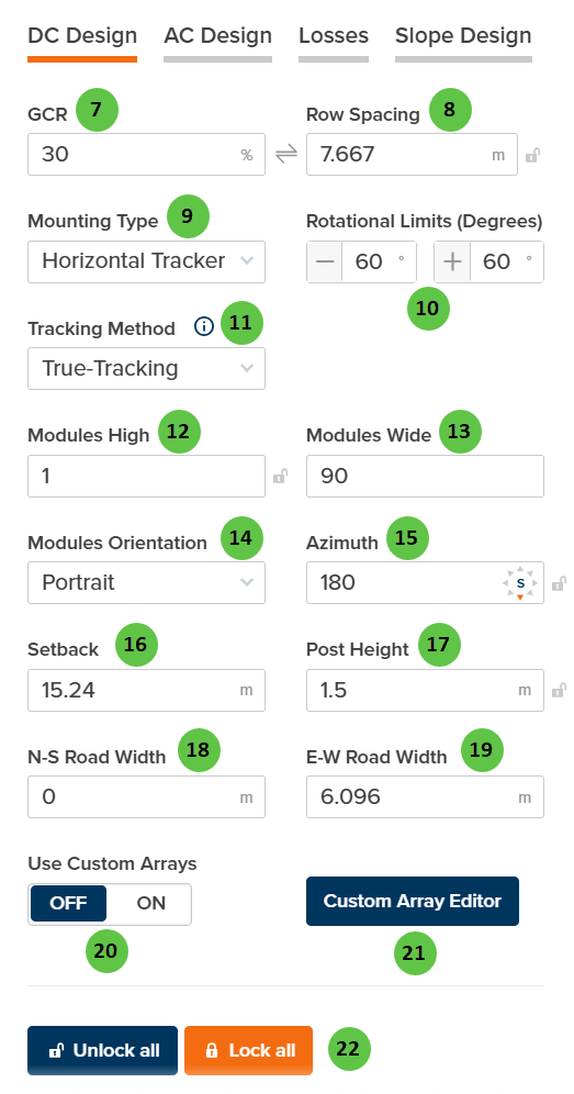
| # | Input | Type | Units | Description | Related Documentation |
|---|---|---|---|---|---|
| 7 | GCR | Text Field | % | Ground Coverage Ratio — the ratio of module area to ground area. Higher GCR means denser packing but increased inter-row shading. Linked to Row Spacing. | Table |
| 8 | Row Spacing | Text Field | m | Distance between tracker rows (pitch). Automatically calculated from GCR and collector width, or can be manually entered. Use the lock icon to toggle between linked and manual modes. | Table |
| 9 | Mounting Type | Dropdown | — | Select between Horizontal Tracker (single-axis tracking that follows the sun) or Fixed Tilt (stationary racking at a fixed angle). Selection affects available tracking parameters. | Tracking Overview |
| 10 | Rotational Limits (Degrees) | Text Fields | degrees | Minimum and maximum rotation angles for the tracker. Typical values are ±60°. The tracker will not rotate beyond these limits. Only available when Mounting Type is Horizontal Tracker. | True Tracking |
| 11 | Tracking Method | Dropdown | — | Select the tracking algorithm. Options: True-Tracking (tracks sun position directly), Backtracking (reduces inter-row shading at low sun angles), Time Series (uses imported tracker angle data). Only available when Mounting Type is Horizontal Tracker. | Backtracking, True Tracking |
| 12 | Modules High | Text Field | — | Number of modules stacked vertically (perpendicular to tracker axis). Use the lock icon to toggle between linked and manual modes. | Table |
| 13 | Modules Wide | Text Field | — | Total number of modules along the tracker length. Use the lock icon to toggle between linked and manual modes. | Table |
| 14 | Modules Orientation | Dropdown | — | Select Portrait (long edge vertical) or Landscape (long edge horizontal) module orientation on the racking. | Table |
| 15 | Azimuth | Text Field | degrees | The compass direction the modules face (0° = North, 90° = East, 180° = South, 270° = West). For trackers, this is the axis orientation. Use the lock icon to toggle between linked and manual modes. | Fixed Tilt Arrays |
| 16 | Setback | Text Field | m | Default setback distance from site boundaries. Arrays will be placed with this minimum distance from the site perimeter. | — |
| 17 | Post Height | Text Field | m | Height of the tracker post (hub height) above ground. Affects bifacial irradiance calculations and ground clearance. | Bifacial Irradiance |
| 18 | N-S Road Width | Text Field | m | Width of access roads running North-South through the site. Used for layout planning and land utilization calculations. | — |
| 19 | E-W Road Width | Text Field | m | Width of access roads running East-West through the site. Used for layout planning and land utilization calculations. | — |
| 20 | Use Custom Arrays | Toggle | — | When ON, the automated layout uses DC block configurations defined in the Custom Array Editor. When OFF, standard block configurations based on the parameters above are used. Manual placement of custom array blocks is still possible regardless of this setting. | Custom Array Editor |
| 21 | Custom Array Editor | Button | — | Opens the Custom Array Editor interface where you can define custom DC block configurations with specific table arrangements and dimensions. | Custom Array Editor |
| 22 | Unlock all / Lock all | Buttons | — | Unlock all enables manual entry for all linked fields. Lock all enables automatic calculation of dependent values based on other inputs. | — |
AC Design
Configure inverter setpoints, transformer settings, and electrical system parameters.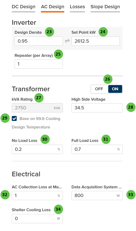
| # | Input | Type | Units | Description | Related Documentation |
|---|---|---|---|---|---|
| 23 | Design Derate | Text Field | — | Fractional derate factor applied to the inverter rated power (0 to 1). Linked to Set Point kW — editing one updates the other. A value of 0.95 means the inverter operates at 95% of rated capacity. | Inverter |
| 24 | Set Point kW | Text Field | kW | Maximum AC power output setpoint for the inverter. Used for power curtailment or plant-level power limiting. Linked to Design Derate — editing one updates the other. | Inverter Models |
| 25 | Repeater (per Array) | Text Field | — | Number of identical inverter/DC Field combinations within each Array. Each repeat uses the same inverter model and DC Field configuration. | Inverter |
| 26 | Transformer | Toggle | — | When ON, enables transformer modeling for each inverter/array. When enabled, transformer losses and specifications are included in the simulation. | — |
| 27 | kVA Rating | Text Field | kVA | Apparent power rating of the transformer. Only available when Transformer toggle is ON. | — |
| 28 | High Side Voltage | Text Field | kV | Transformer high-side (grid-side) voltage. Only available when Transformer toggle is ON. | — |
| 29 | Base on 99.6 Cooling Design Temperature | Checkbox | — | When enabled, the kVA rating is adjusted based on the site’s 99.6% cooling design temperature from ASHRAE data. This accounts for temperature-based derating of transformer capacity. | — |
| 30 | No Load Loss | Text Field | % | Transformer core losses that occur whenever the transformer is energized, regardless of load. Also known as iron losses or excitation losses. Only available when Transformer toggle is ON. | AC Losses |
| 31 | Full Load Loss | Text Field | % | Transformer copper losses at full rated load. These losses scale with the square of the load current. Only available when Transformer toggle is ON. | AC Losses |
| 32 | AC Collection Loss at Max Power | Text Field | % | Percentage loss in the AC collection system (medium voltage cables, switchgear) at maximum power output. | AC System Losses |
| 33 | Data Acquisition System Power | Text Field | W | Parasitic power consumption of the monitoring and data acquisition system. | — |
| 34 | Shelter Cooling Loss | Text Field | W | Parasitic power consumption of inverter shelter cooling systems (HVAC for enclosed inverter stations). | — |
Losses
Configure DC loss factors and thermal model parameters that affect energy yield calculations.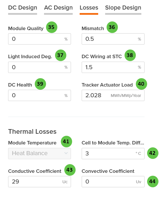
| # | Input | Type | Units | Description | Related Documentation |
|---|---|---|---|---|---|
| 35 | Module Quality | Text Field | % | Percentage loss due to module manufacturing quality variation from nameplate rating. Positive values indicate underperformance relative to rated power. | DC Losses |
| 36 | Mismatch | Text Field | % | Percentage loss due to electrical mismatch between modules in a string or array. Accounts for variations in module I-V characteristics. | DC Losses |
| 37 | Light Induced Deg. | Text Field | % | Percentage loss from initial light-induced degradation (LID) that occurs in the first hours of module operation. Applies primarily to crystalline silicon modules. | DC Losses |
| 38 | DC Wiring at STC | Text Field | % | Percentage loss in DC wiring and connections at Standard Test Conditions (STC). Includes string wiring, combiner boxes, and DC home runs. | DC Losses |
| 39 | DC Health | Text Field | % | Percentage loss representing ongoing DC system degradation and health issues not captured by other loss categories. Can be used for aging adjustments. | DC Losses |
| 40 | Tracker Actuator Load | Text Field | MWh/MWp/Year | Annual energy consumption of tracker motors and actuators, expressed per MWp of DC capacity. Only applicable to tracker-mounted systems. | Losses |
| 41 | Module Temperature | Dropdown | — | Select the module temperature calculation method. Options: Heat Balance (detailed thermal model), Sandia (empirically-derived coefficients), NOCT (Nominal Operating Cell Temperature method). | Module Temperature |
| 42 | Cell to Module Temp. Diff. | Text Field | °C | Temperature offset between the module backsheet (measured) and cell junction temperature. Accounts for thermal resistance within the module. | Module Temperature |
| 43 | Conductive Coefficient | Text Field | Uc | Conductive heat transfer coefficient (Uc) for the Heat Balance model. Represents constant heat loss independent of wind speed. Only visible when Module Temperature is set to Heat Balance. | Heat Balance |
| 44 | Convective Coefficient | Text Field | Uv | Convective heat transfer coefficient (Uv) for the Heat Balance model. Represents wind-dependent heat loss; multiplied by wind speed in the thermal calculation. Only visible when Module Temperature is set to Heat Balance. | Heat Balance |
Slope Design
Choose the plant layout mode and configure terrain-related options that affect how the automated layout handles sloped sites.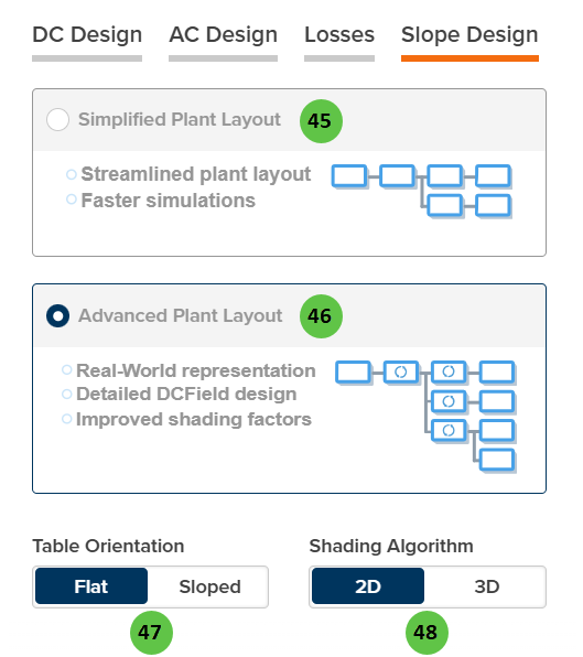
| # | Input | Type | Units | Description | Related Documentation |
|---|---|---|---|---|---|
| 45 | Simplified Plant Layout | Radio Button | — | Default mode. Creates a streamlined plant layout with typical blocks and uses average DC/AC ratios across the plant. Results in faster simulations and fewer unique DC Field configurations. Best for preliminary design and rapid iteration. | — |
| 46 | Advanced Plant Layout | Radio Button | — | Optional mode. Creates detailed DC Fields with DC/AC ratios as configured in the actual layout. Results in more unique DC Fields and Inverters, providing real-world representation and improved shading factor accuracy. Processing times are longer due to increased complexity. When selected, Table Orientation and Shading Algorithm options become available. | — |
| 47 | Table Orientation | Toggle | — | Flat (default): Tables are oriented horizontally regardless of terrain. Sloped: Computes average slope based on topographical data and orients tables to follow terrain. Only available when Advanced Plant Layout is selected. | Field |
| 48 | Shading Algorithm | Toggle | — | 2D (default): Uses 2D linear shading calculations for inter-row shading. 3D: Uses 3D shading model for more accurate representation of shade patterns on sloped terrain. Only available when Advanced Plant Layout is selected. | Row-to-Row Beam Shading, 3D Shading |