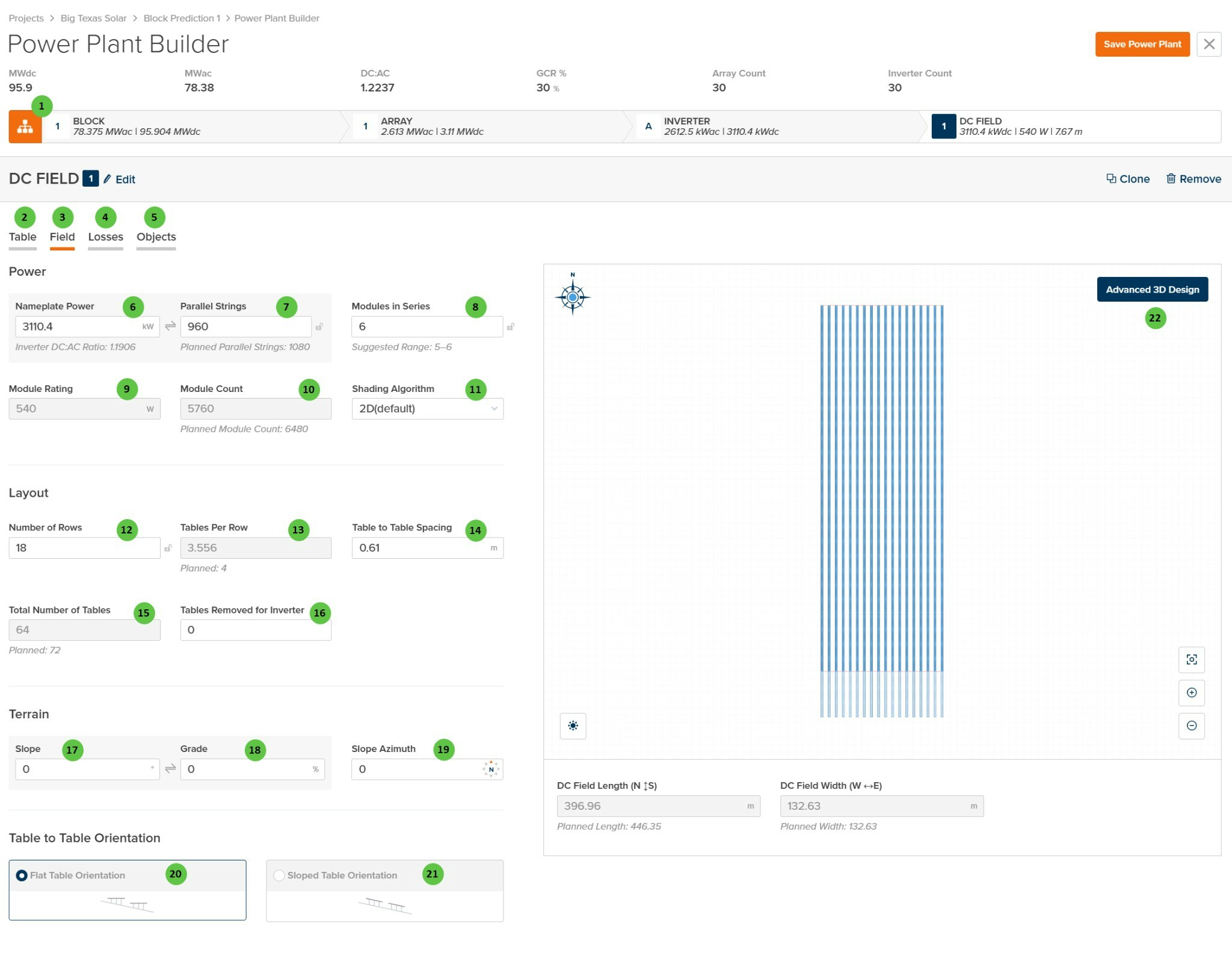
| 1 | Edit (DC Field) | Button | — | Opens a dialog to edit the DC Field name and repeater count. | — |
| 2 | Table (Tab) | Tab | — | Navigate to the Table tab to configure module selection, mounting type, and table geometry. | Table |
| 3 | Field (Tab) | Tab | — | Currently selected tab. Contains DC Field layout, power configuration, and terrain settings. | — |
| 4 | Losses (Tab) | Tab | — | Navigate to the Losses tab to configure DC field losses including mismatch, wiring losses, and thermal model parameters. | Losses |
| 5 | Objects (Tab) | Tab | — | Navigate to the Objects tab to configure near-field shading objects specific to this DC Field (legacy workflow). | Objects |
| 6 | Nameplate Power | Text Field | kW | The total DC nameplate power of the DC Field. Calculated from Module Rating × Module Count. Displays the Inverter DC:AC Ratio below for reference. | — |
| 7 | Parallel Strings | Text Field | — | Number of strings connected in parallel to the inverter from this DC Field. “Planned Parallel Strings” shown below indicates the target value based on inverter sizing. | — |
| 8 | Modules in Series | Text Field | — | Number of modules connected in series per string. The “Suggested Range” indicates valid values based on inverter voltage limits and module Voc/Vmp characteristics. | — |
| 9 | Module Rating | Display | W | The rated power of the selected module. This value is read-only and is set on the Table tab via module selection. | — |
| 10 | Module Count | Text Field | — | Total number of modules in the DC Field. Calculated from Parallel Strings × Modules in Series. “Planned Module Count” indicates the target based on layout. | — |
| 11 | Shading Algorithm | Dropdown | — | Select the shading calculation method. Options: 2D (default), Infinite Length Rows, 3D (Legacy). | Row-to-Row Beam Shading |
| 12 | Number of Rows | Text Field | — | The number of tracker or fixed-tilt rows in the DC Field. Use the sync icon to toggle between linked and manual modes. | — |
| 13 | Tables Per Row | Text Field | — | Average number of tables per row. May be a decimal if rows have varying table counts. “Planned” value shown below indicates the target configuration. | — |
| 14 | Table to Table Spacing | Text Field | m / ft | Horizontal gap between adjacent tables along a row. Used for layout visualization and land area calculations. | — |
| 15 | Total Number of Tables | Text Field | — | Total count of tables in the DC Field. Calculated from Number of Rows × Tables Per Row, minus any removed tables. “Planned” value indicates target. | — |
| 16 | Tables Removed for Inverter | Text Field | — | Number of tables removed from the layout to accommodate inverter pad placement or other obstructions. | — |
| 17 | Slope | Text Field | degrees | Ground slope angle of the DC Field terrain. Affects bifacial calculations and terrain-aware backtracking if enabled. | Terrain-Aware Backtracking |
| 18 | Grade | Text Field | % | Ground slope expressed as a percentage (rise/run × 100). Linked to Slope field — editing one updates the other. | — |
| 19 | Slope Azimuth | Text Field | degrees | Compass direction of the downhill slope (0° = North, 90° = East, 180° = South, 270° = West). | — |
| 20 | Flat Table Orientation | Radio Button | — | Tables are oriented horizontally regardless of terrain slope. Standard configuration for level or gently sloped sites. | — |
| 21 | Sloped Table Orientation | Radio Button | — | Tables follow the terrain slope, maintaining consistent height above ground across sloped terrain. | — |
| 22 | Advanced 3D Design | Button | — | Opens the advanced 3D design interface for detailed field layout customization, including individual row placement and terrain modeling. | 3D Shading |