Overview
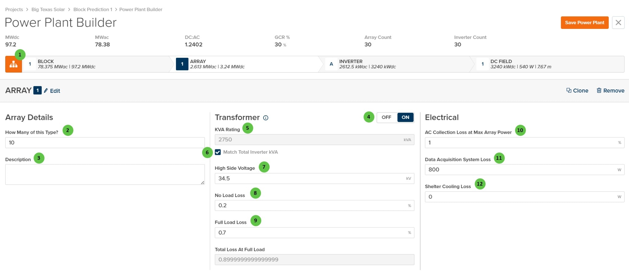
The Array page is organized into the following sections:- Hierarchy Bar — Shows the current position in the plant hierarchy (Block → Array → Inverter → DC Field) with system capacity summaries.
- Array Header — Displays the array identifier with Edit, Clone, and Remove buttons.
- Array Details — Define how many arrays of this type exist and add optional notes.
- Transformer — Configure the MV transformer including kVA rating, voltage, and loss parameters. The transformer can be toggled on or off.
- Electrical — Configure AC collection losses including wiring losses and auxiliary power consumption.
User Inputs
| # | Input | Type | Units | Description | Related Documentation |
|---|---|---|---|---|---|
| 1 | Block (Hierarchy) | Button | — | Toggle view to show the hierarchy bar displaying system summary at each level: Block, Array, Inverter, and DC Field. Shows MWdc, MWac, DC:AC ratio, GCR, Array Count, and Inverter Count. | Block Overview |
| 2 | How Many of this Type? | Text Field | — | Number of identical arrays within this Block. Each repeat uses the same transformer, inverter, and DC Field configuration. Useful for modeling uniform plant sections without duplicating design work. | — |
| 3 | Description | Text Area | — | Optional text field for notes or comments about this array configuration. Does not affect simulation results. | — |
| 4 | Transformer (Toggle) | Toggle | — | Enable or disable the MV transformer for this array. When OFF, transformer losses are not applied and the transformer configuration fields are hidden. When ON, the transformer parameters below become active. | AC System Losses |
| 5 | KVA Rating | Text Field | kVA | Apparent power rating of the MV transformer. Can be manually entered or automatically matched to the total inverter kVA rating using the checkbox below. | AC System Losses |
| 6 | Match Total Inverter kVA | Checkbox | — | When checked, the transformer kVA rating is automatically set to match the sum of all inverter kVA ratings in the array. Uncheck to manually specify a different transformer size. | — |
| 7 | High Side Voltage | Text Field | kV | Medium-voltage output of the transformer (high side). Typical values range from 12 kV to 69 kV depending on the collection system design. | — |
| 8 | No Load Loss | Text Field | % | Transformer core losses as a percentage of rated kVA. These losses occur whenever the transformer is energized, regardless of load. Also known as iron losses or excitation losses. | AC System Losses |
| 9 | Full Load Loss | Text Field | % | Transformer winding losses at full load as a percentage of rated kVA. Also known as copper losses or load losses. Scales with the square of the load. | AC System Losses |
| 10 | AC Collection Loss at Max Array Power | Text Field | % | Resistive losses in the MV collection circuit at maximum array power output. Includes cable and connection losses between the transformer and the point of interconnection. | AC System Losses |
| 11 | Data Acquisition System Loss | Text Field | W | Constant power consumption of data acquisition and monitoring equipment (SCADA, meters, sensors, communication systems) at the array level. | — |
| 12 | Shelter Cooling Loss | Text Field | W | Constant power consumption for inverter shelter or equipment enclosure cooling systems (HVAC, fans). Set to 0 if no active cooling is used. | — |