The Energy Storage System page allows you to configure an optional AC-coupled battery energy storage system (BESS) for your prediction. To enable energy storage, enter a Nameplate capacity value (input #1) and an Inverter Real Power rating (input #9). The Dispatch Algorithm should also be configured to ensure the battery charges and discharges appropriately.
Energy storage is optional for predictions. If no values are entered, the prediction runs without battery storage. This is an AC-coupled configuration where the battery system connects at the AC bus alongside the PV system.
Energy Capacity
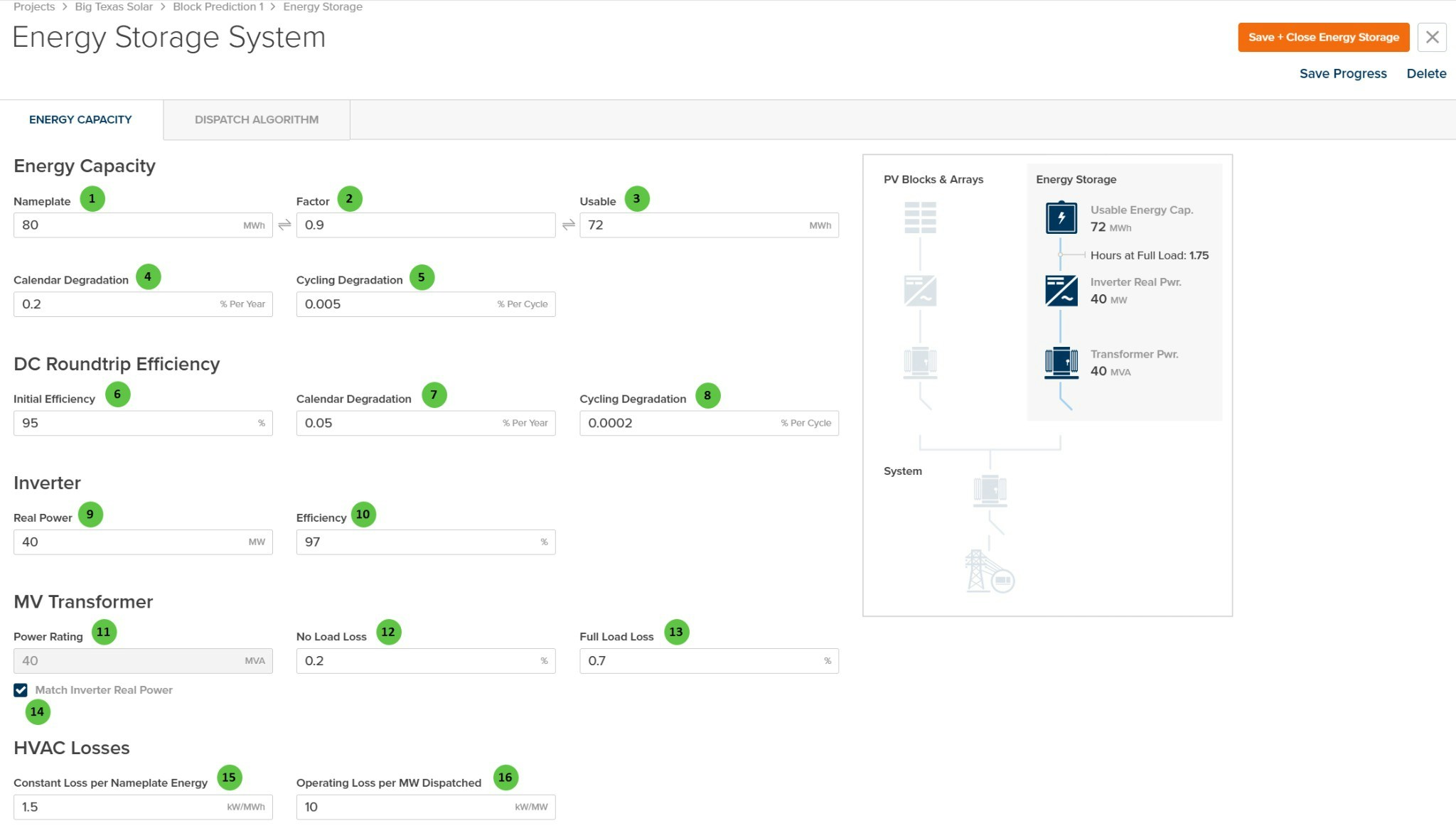
The Energy Capacity tab configures the battery capacity, degradation rates, DC roundtrip efficiency, inverter, MV transformer, and HVAC losses.
Overview
The Energy Capacity tab is organized into the following sections:
- Energy Capacity — Define nameplate and usable capacity with degradation parameters.
- DC Roundtrip Efficiency — Configure battery efficiency and efficiency degradation over time.
- Inverter — Specify the battery inverter power rating and efficiency.
- MV Transformer — Configure the medium-voltage transformer for the storage system.
- HVAC Losses — Define thermal management power consumption.
- System Diagram — Visual representation showing how the energy storage connects to the PV system.
| # | Input | Type | Units | Description | Related Documentation |
|---|
| 1 | Nameplate | Text Field | MWh | Total nameplate energy capacity of the battery system. Required to enable energy storage. This is the manufacturer-rated capacity before applying the usable factor. | — |
| 2 | Factor | Text Field | — | Usable capacity factor (0 to 1). Represents the fraction of nameplate capacity that is actually usable, accounting for depth-of-discharge limits and reserve margins. Linked to Usable — editing one updates the other. | — |
| 3 | Usable | Text Field | MWh | Usable energy capacity calculated as Nameplate × Factor. This is the actual available capacity for charging and discharging operations. Linked to Factor — editing one updates the other. | — |
| 4 | Calendar Degradation | Text Field | % Per Year | Annual capacity degradation due to calendar aging (time-based). Applied regardless of cycling activity. Reduces usable capacity over the system lifetime. | — |
| 5 | Cycling Degradation | Text Field | % Per Cycle | Capacity degradation per charge/discharge cycle. Applied based on actual cycling activity during the simulation. Combined with calendar degradation for total capacity loss. | — |
| 6 | Initial Efficiency | Text Field | % | DC roundtrip efficiency of the battery system at initial conditions. Represents the ratio of energy discharged to energy charged, accounting for internal losses. | — |
| 7 | Calendar Degradation (Efficiency) | Text Field | % Per Year | Annual efficiency degradation due to calendar aging. Reduces roundtrip efficiency over time regardless of cycling. | — |
| 8 | Cycling Degradation (Efficiency) | Text Field | % Per Cycle | Efficiency degradation per charge/discharge cycle. Applied based on actual cycling activity. | — |
| 9 | Real Power | Text Field | MW | Rated real power of the battery inverter. Required to enable energy storage. Determines maximum charge and discharge power rates. | — |
| 10 | Efficiency | Text Field | % | Inverter conversion efficiency from DC to AC (discharge) and AC to DC (charge). Applied in addition to battery roundtrip efficiency. | — |
| 11 | Power Rating | Text Field | MVA | Apparent power rating of the MV transformer for the storage system. Can be manually entered or automatically matched to inverter power using the checkbox below. | — |
| 12 | No Load Loss | Text Field | % | Transformer core losses as a percentage of rated MVA. These losses occur whenever the transformer is energized, regardless of load. | AC System Losses |
| 13 | Full Load Loss | Text Field | % | Transformer winding losses at full load as a percentage of rated MVA. Scales with the square of the load. | AC System Losses |
| 14 | Match Inverter Real Power | Checkbox | — | When checked, the transformer power rating is automatically set to match the inverter real power rating. Uncheck to manually specify a different transformer size. | — |
| 15 | Constant Loss per Nameplate Energy | Text Field | kW/MWh | Baseline HVAC power consumption proportional to nameplate capacity. Represents thermal management load required regardless of dispatch activity. | — |
| 16 | Operating Loss per MW Dispatched | Text Field | kW/MW | Additional HVAC power consumption proportional to dispatch power. Accounts for increased cooling requirements during active charging or discharging. | — |
Dispatch Algorithm
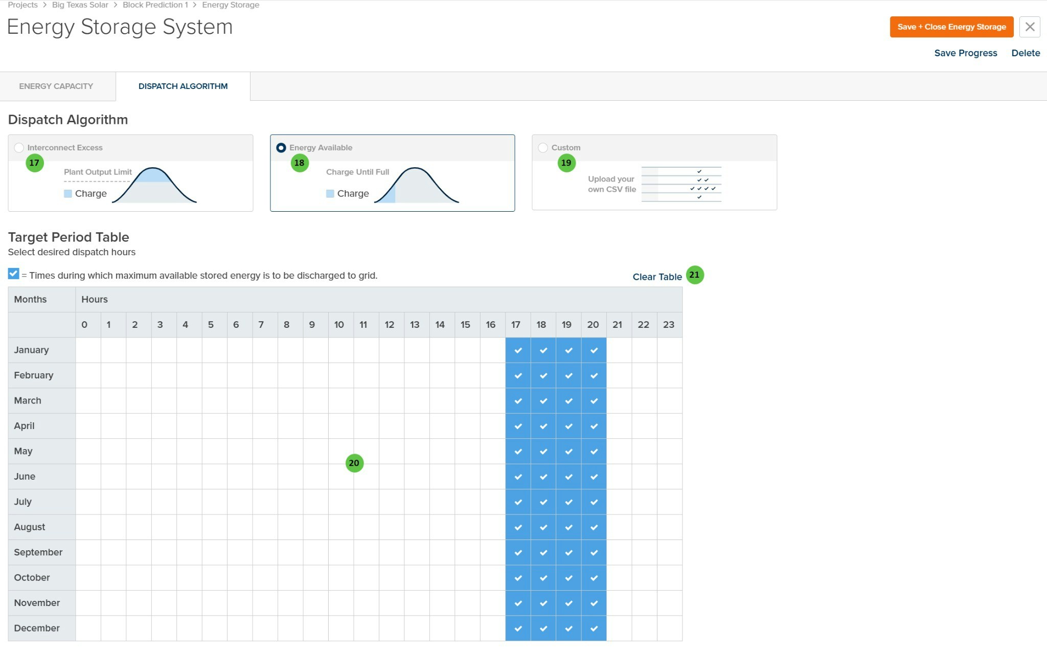
The Dispatch Algorithm tab configures how the battery charges and discharges throughout the simulation. Proper configuration ensures the battery operates according to your intended use case (e.g., peak shaving, energy arbitrage, capacity firming).
Overview
The Dispatch Algorithm tab is organized into the following sections:
- Dispatch Mode Selection — Choose between three charging strategies: Interconnect Excess, Energy Available, or Custom.
- Target Period Table — Define the hours during which the battery should discharge stored energy to the grid.
| # | Input | Type | Units | Description | Related Documentation |
|---|
| 17 | Interconnect Excess | Radio Button | — | Charges the battery when PV production exceeds the plant output limit (interconnection capacity). The battery stores clipped energy that would otherwise be curtailed, then discharges during target periods. | — |
| 18 | Energy Available | Radio Button | — | Charges the battery whenever energy is available from the PV system until full capacity is reached. Discharges during target periods. This mode maximizes battery utilization for energy shifting. | — |
| 19 | Custom | Radio Button | — | Upload a custom CSV file defining charge/discharge behavior for each timestamp. Provides maximum flexibility for complex dispatch strategies or externally-optimized schedules. | — |
| 20 | Target Period Table | Interactive Table | — | Click cells to select the hours (columns 0–23) and months (rows January–December) during which maximum available stored energy should be discharged to the grid. Selected cells show a checkmark. Typically set to peak demand hours for energy arbitrage. | — |
| 21 | Clear Table | Button | — | Clears all selected cells in the Target Period Table, removing all discharge period selections. | — |
Saving Changes
Click Save + Close Energy Storage to save all configuration changes and return to the prediction. Click Save Progress to save without closing. Click Delete to remove the energy storage system from the prediction. Click the X button to close without saving.