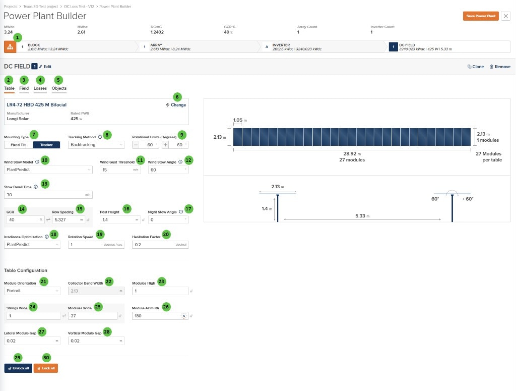
| 1 | Edit (DC Field) | Button | — | Opens a dialog to edit the DC Field name and repeater count. | — |
| 2 | Table (Tab) | Tab | — | Currently selected tab. Contains module selection, mounting type, tracker settings, and table geometry configuration. | — |
| 3 | Field (Tab) | Tab | — | Navigate to the Field tab to configure string count, layout arrangement, terrain, and field-level settings. | Field |
| 4 | Losses (Tab) | Tab | — | Navigate to the Losses tab to configure DC field losses including mismatch, wiring losses, and thermal model parameters. | Losses |
| 5 | Objects (Tab) | Tab | — | Navigate to the Objects tab to configure near-field shading objects specific to this DC Field (legacy workflow). | Objects |
| 6 | Change (Module) | Button | — | Opens the module selection dialog to choose a different PV module. Displays current module manufacturer, model name, and rated power (W). | Module Library, Module File |
| 7 | Mounting Type | Toggle | — | Select between Fixed Tilt (stationary racking at a fixed angle) or Tracker (single-axis tracking that follows the sun). Tracker is shown in this example. | Tracking Overview |
| 8 | Tracking Method | Dropdown | — | Select the tracking algorithm. Options: True Tracking, Backtracking, Time Series. Only available when Mounting Type is Tracker. | Backtracking |
| 9 | Rotational Limits (Degrees) | Text Fields | degrees | Minimum and maximum rotation angles for the tracker. Typical values are ±60°. The tracker will not rotate beyond these limits. | True Tracking |
| 10 | Wind Stow Model | Dropdown | — | Select the wind stow behavior model. Options: Disabled, PlantPredict, Array Technologies. Controls how the tracker responds to high wind conditions. | Wind Stow |
| 11 | Wind Gust Threshold | Text Field | m/s / ft/s | Wind speed threshold that triggers stow behavior. When wind exceeds this value, the tracker moves to the stow angle. | Wind Stow |
| 12 | Wind Stow Angle | Text Field | degrees | The angle to which the tracker rotates during high wind conditions. Typically a high angle (e.g., 60°) to reduce wind load. | Wind Stow |
| 13 | Stow Dwell Time | Text Field | min | Time that wind gust must remain continuously at or below the Wind Gust Threshold before the tracker returns to normal operation after a wind stow. Shown only when Wind Stow Model is PlantPredict. Integer ≥ 0; default 30 for new DC Fields. Null or missing values are treated as 0 (no dwell delay) for older projects. If gust exceeds the threshold again before the dwell completes, the wait restarts. | Wind Stow |
| 14 | GCR | Text Field | % | Ground Coverage Ratio — the ratio of module area to ground area. Higher GCR means denser packing. Linked to Row Spacing. | — |
| 15 | Row Spacing | Text Field | m / ft | Distance between tracker rows (pitch). Automatically calculated from GCR and collector width, or can be manually entered. Use the sync icon to toggle between linked and manual modes. | — |
| 16 | Post Height | Text Field | m / ft | Height of the tracker post (hub height) above ground. Affects bifacial irradiance calculations and clearance. | Bifacial Irradiance |
| 17 | Night Stow Angle | Text Field | degrees | The angle to which the tracker returns at night or during non-tracking periods. Availability controlled by Model Choices settings. | — |
| 18 | Irradiance Optimization | Dropdown | — | Select the irradiance optimization algorithm for tracker angle calculation. Options: None, PlantPredict, Array Technologies. Availability controlled by Model Choices settings. | Irradiance Optimization |
| 19 | Rotation Speed | Text Field | degrees/sec | The speed at which the tracker rotates. Used in irradiance optimization calculations. Availability controlled by Model Choices settings. | Irradiance Optimization |
| 20 | Hesitation Factor | Text Field | decimal | A factor (0-1) that controls tracker response to irradiance changes. Higher values mean more hesitation before moving. Availability controlled by Model Choices settings. | Irradiance Optimization |
| 21 | Module Orientation | Dropdown | — | Select Portrait (long edge vertical) or Landscape (long edge horizontal) module orientation on the racking. | — |
| 22 | Collector Band Width | Text Field | m / ft | The total width of the module array on the tracker (perpendicular to the axis of rotation). Calculated from module dimensions and Modules High. | — |
| 23 | Modules High | Text Field | — | Number of modules stacked vertically (perpendicular to tracker axis). Use the sync icon to toggle between linked and manual modes. | — |
| 24 | Strings Wide | Text Field | — | Number of strings arranged along the tracker length. Use the sync icon to toggle between linked and manual modes. | — |
| 25 | Modules Wide | Text Field | — | Total number of modules along the tracker length. Calculated from Strings Wide × modules per string. Use the sync icon to toggle between linked and manual modes. | — |
| 26 | Module Azimuth | Text Field | degrees | The compass direction the modules face (0° = North, 90° = East, 180° = South, 270° = West). For trackers, this is the axis orientation. Use the sync icon to toggle between linked and manual modes. | Fixed Tilt Arrays |
| 27 | Lateral Module Gap | Text Field | m / ft | Horizontal gap between adjacent modules along the tracker length. | — |
| 28 | Vertical Module Gap | Text Field | m / ft | Vertical gap between modules when Modules High > 1. | — |
| 29 | Unlock all | Button | — | Unlocks all linked fields, allowing manual entry of values that would otherwise be automatically calculated. | — |
| 30 | Lock all | Button | — | Locks all linkable fields, enabling automatic calculation of dependent values based on other inputs. | — |