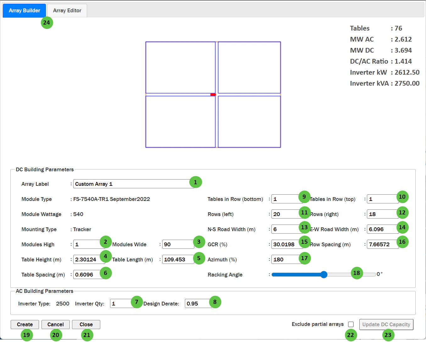
| 1 | Array Label | Text Field | — | User-defined name for this custom array configuration. Used to identify the array when placing it on the map or selecting it from the Array Editor. | — |
| 2 | Modules High | Text Field | — | Number of modules stacked vertically (perpendicular to tracker axis or along the tilt direction for fixed systems). | Table |
| 3 | Modules Wide | Text Field | — | Total number of modules along the tracker length or row direction. | Table |
| 4 | Table Height | Text Field | m / ft | Height of the table (collector band width) calculated from module dimensions and Modules High. | — |
| 5 | Table Length | Text Field | m / ft | Length of the table calculated from module dimensions and Modules Wide. | — |
| 6 | Table Spacing | Text Field | m / ft | Horizontal gap between adjacent tables along a row. | — |
| 7 | Inverter Qty | Text Field | — | Number of inverters in this custom array block. Affects the total AC capacity calculation. | Inverter |
| 8 | Design Derate | Text Field | — | Fractional derate factor applied to the inverter rated power (0 to 1). A value of 0.95 means the inverter operates at 95% of rated capacity. | Inverter |
| 9 | Tables in Row (bottom) | Text Field | — | Number of tables in each row of the bottom section of the array (below the E-W road). | — |
| 10 | Tables in Row (top) | Text Field | — | Number of tables in each row of the top section of the array (above the E-W road). | — |
| 11 | Rows (left) | Text Field | — | Number of rows in the left section of the array (west of the N-S road). | — |
| 12 | Rows (right) | Text Field | — | Number of rows in the right section of the array (east of the N-S road). | — |
| 13 | N-S Road Width | Text Field | m / ft | Width of the North-South oriented access road that divides the array into left and right sections. | — |
| 14 | E-W Road Width | Text Field | m / ft | Width of the East-West oriented access road that divides the array into top and bottom sections. | — |
| 15 | GCR (%) | Text Field | % | Ground Coverage Ratio — the ratio of module area to ground area. Higher GCR means denser packing. Linked to Row Spacing. | Table |
| 16 | Row Spacing | Text Field | m / ft | Distance between tracker rows (pitch). Automatically calculated from GCR and collector width, or can be manually entered. | Table |
| 17 | Azimuth | Text Field | degrees | The compass direction the modules face (0° = North, 90° = East, 180° = South, 270° = West). For trackers, this is the axis orientation. Accepts decimal values for precise orientation control. | Fixed Tilt Arrays, Tracking Overview |
| 18 | Racking Angle | Slider | degrees | The tilt angle of the racking system. For trackers, this represents the current tracker angle position for the preview. For fixed-tilt systems, this is the fixed tilt angle. | Fixed Tilt Arrays, Tracking Overview |
| 19 | Create | Button | — | Places the custom array on the map at a location you specify. After clicking, you can position the array block on the map canvas. | — |
| 20 | Cancel | Button | — | Cancels the current array configuration without saving changes. | — |
| 21 | Close | Button | — | Closes the Custom Array Editor dialog and returns to the map interface. | — |
| 22 | Exclude partial arrays | Checkbox | — | When enabled, the automated layout uses only the custom array shapes and configurations as defined in the Custom Array Editor. Partial arrays will not be automatically generated, which may result in lower capacity and land utilization. | — |
| 23 | Update DC Capacity | Button | — | Applies the custom array configurations to the automated layout. Requires Use Custom Arrays to be toggled on in Power Plant Parameters. The layout engine will use these custom block shapes when filling the site boundaries. | Power Plant Parameters |
| 24 | Array Builder / Array Editor Tabs | Tab Toggle | — | Toggle between Array Builder and Array Editor tabs. Array Builder (shown by default) is used to build full array blocks. Array Editor allows you to break the array block apart for rack-by-rack editing on the map UI. | — |