PlantPredict
New Features & Updates!
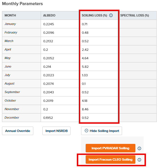
- Fracsun Soiling Loss Integration - It is now possible to import monthly soiling losses from Fracsun CLEO for any project location in the continental US! This can be accessed from the Environmental Conditions / Weather page within a Prediction. Read more about CLEO AI - PV Soiling Loss Modeling Tool
- AC Collection Loss Enhancements - PlantPredict now applies a more realistic ohmic (I^2 x R) calculation method to the AC Collection Loss, similar to the DC Wiring Loss. The user entered AC Collection Loss percentage is applied at maximum Array Power (Maximum Inverter Power x Number of Inverters), similar to how the DC Wiring Loss percentage is applied at STC power level. At power levels other than maximum Array Power, the percental loss will vary with the square of the current through the collection circuit. This is change is described in detail here: AC Collection System Note - This change will only applied to predictions run on Version 12 and later.
- PPD Import Improvements - When using the “Import Predictions” button (from within an existing project), if the selected .PPD file has assets (weather, module, inverter) which the importing user already has access to, we will no longer create a new assets. Assets will only be created if the importing user cannot otherwise access them in the system. This helps to avoid duplicated assets where PPD files are being shared within the same company.
- MapBuilder Multi-Parcel Selection Improvements - When selecting multiple parcels in MapBuilder (holding down the Shift key), parcel information for the last parcel selected is displayed. This improvement has been recommended by several customers. Previously, this information was suppressed when multiple parcels where selected.
- MapBuilder Boundary Setback Improvements - MapBuilder boundary setback distance limitations of 50m have been removed, allowing for larger setback to be applied.
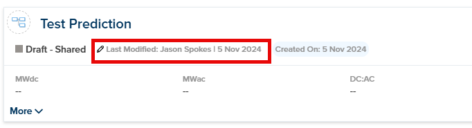
- Prediction Information Panel Improvements - Additional data has been added to the Prediction card to display Last Modified User and Date:
- 3D Shade Scene Usability Improvements - PlantPredict now displays a warning message and disables the “Queue 3D Calculations” button when PVC files containing more than 30,000 shading objects are uploaded.
Bug Fixes
- LeTID and Degradation losses were sometimes reported as non-zero (i.e., 0.01%) on the losses tree, even if set to 0%. This has been corrected. Note - This change will only applied to predictions run on Version 12 and later.
- Previously, monthly soiling losses would be reverted to default values when importing NSRDB albedo values. And similarly, monthly albedo values would be reverted to default values when importing PVRADAR monthly soiling losses. This has been corrected.
Design Pro
New Features & Updates!
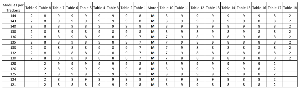
Expanded Configurations for 1P Multi-String Tracker:
- Configurations have been expanded from the previous limit of 120 modules to now support up to 144 modules per tracker.
- The new configurations include various module distributions per table, accommodating higher module counts for more flexible design options.
Bug Fix
Module Orientation for Generic Tracker
The image representing the module orientation for the generic tracker has been updated to reflect the correct positioning.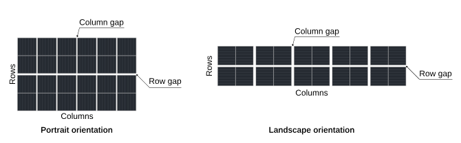
Terrain Pro
New Features & Updates!
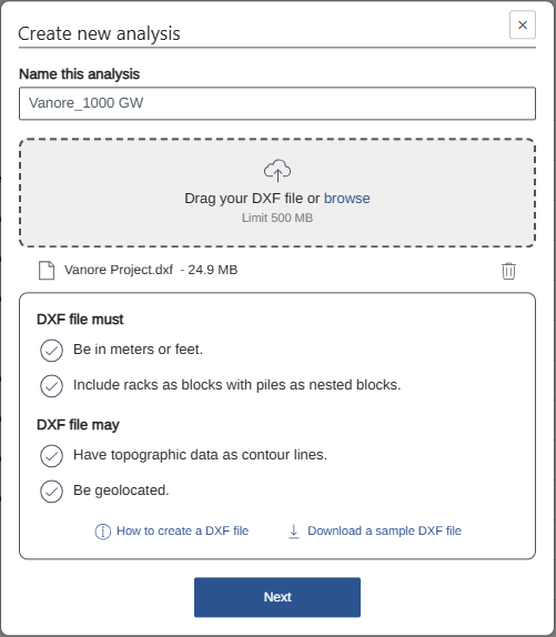
Terrain Pro DXF extension
Terrain Pro DXF extension is now live and ready for use. With this new extension, users can seamlessly import DXF files for advanced terrain analysis, providing greater flexibility and accuracy in earthwork calculations. How to Access: To start using the DXF extension, navigate to the Terabase Apps, select Terrain Pro, and follow the prompts to begin your DXF file import.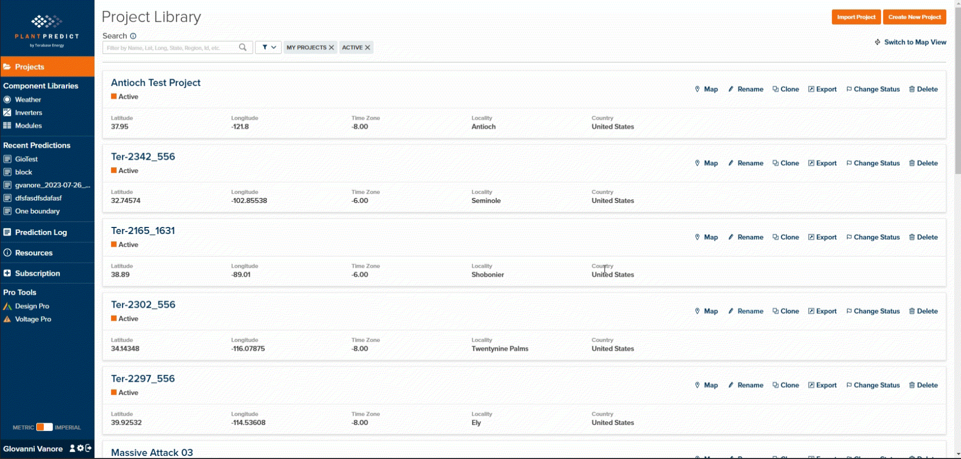
New elevation Data Selection
Users can now select elevation data for their Terrain Pro analysis from either the polylines with elevation data embedded in their uploaded DXF file or the available satellite data for the project location.- Data Selection Flow
If the imported DXF file includes both polylines with elevation and EPSG code, both tabs will be selectable. By default, the user will start on the Contour Line tab with relevant layers already selected.
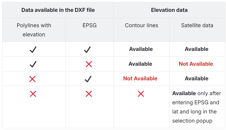
- Contour Line and Satellite Data Tabs
Depending on the data available in the DXF file, users can create an analysis based on the following table:.
- Satellite Data Access
To utilize satellite data, users must provide the EPSG code for the project to accurately convert the coordinate system in the DXF file to match the satellite elevation data’s coordinates. Without an EPSG code, satellite data will not be accessible. - Updated Validation Process
Elevation data in thelwpolylineand EPSG code fields are now optional but require at least one for analysis creation.


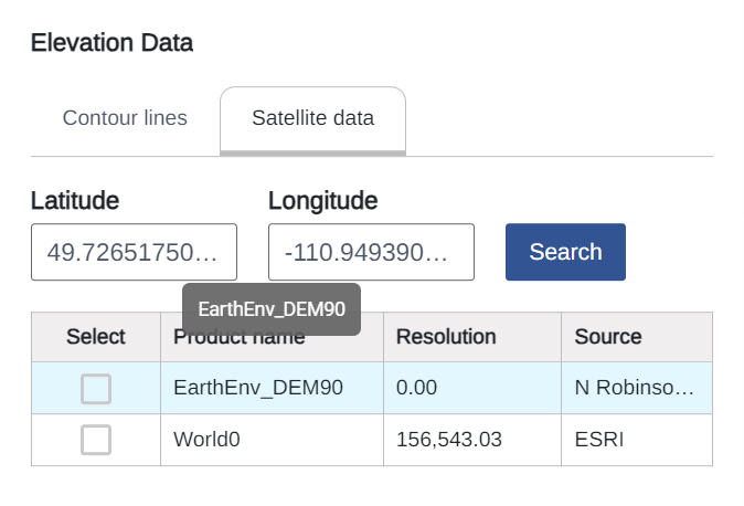
- Satellite Data Tab
Displays the latitude and longitude of the site, determined from the first polyline with elevation and EPSG code. Users can edit and search for updated satellite data if the auto-retrieved coordinates seem incorrect.
- Satellite Data Details
For more details about the satellite data available in Terrain Pro, please refer to the appendix of the Terrain Pro User guide Terrain Pro user guide | Appendix When a satellite dataset is selected, any previous selection from the Contour Line tab will be automatically deselected, as combining both sources for pile coordinate extraction isn’t supported.
Process Variations Based on Data Source
- Contour Line Selection:
The application performs a weeding and supplementing process for polyline points, generates a TIN surface, and extracts ground coordinates for piles. - Satellite Elevation Data Selection:
The application directly extracts rack pile ground coordinates from the satellite dataset without generating a TIN surface.