1 Introduction
1.1 Purpose
Voltage Pro is a cloud-based application that allows users to calculate the maximum string length (i.e., maximum number of modules in series) for a specific photovoltaic module at a specific project location. The application calculates maximum string length under two different methods:- Method 1 – Simplified Linear Approximation
- Method 2 – Plant Predict Advanced Simulation
1.2 Integration with Plant Predict
The Voltage Pro application is tightly integrated with Plant Predict and is accessible with a PlantPredict license. Voltage Pro leverages the Plant Predict weather, module and inverter databases and uses the Plant Predict performance simulation capabilities to calculate open circuit voltages for each time step of a given prediction. When a Project is created in Voltage Pro, a Project of the same name and of type: StringSize is created in Plant Predict. Similarly, when a calculation is created and run in Voltage Pro, a prediction of the same name is created in Plant Predict. The following diagram provides a simple illustration of the relationship: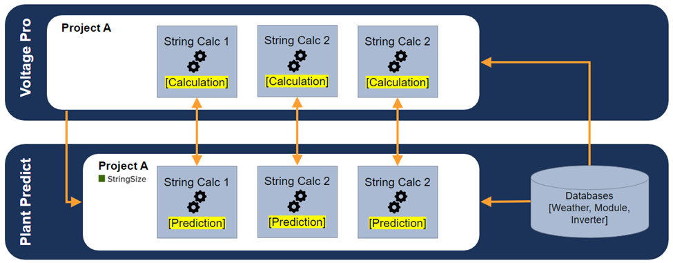
Relationship between Voltage Pro and PlantPredict
1.3 Codes and Standards Compliance
Several codes and standards accept and provide justification for simulation-based string sizing calculations. However, these codes and standards are generally vague in defining exactly how simulation-based calculations should be performed. Terabase, through consultation with industry stakeholders and review of available research, considers the Voltage Pro application to be compliant with the following codes and standards when used with appropriate input data: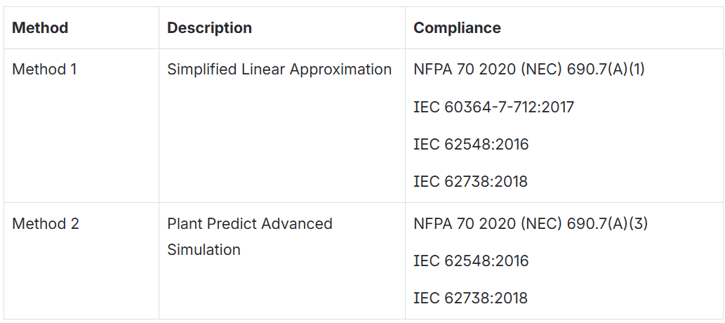
1.4 References
The simulation-based methodology used within Voltage Pro is based in part on the following IEEE Journal of Photovoltaics research: T. Karin and A. Jain, “Photovoltaic String Sizing Using Site-Specific Modeling,” in IEEE Journal of Photovoltaics, vol. 10, no. 3, pp. 888-897, May 2020, doi: 10.1109/JPHOTOV.2020.2969788.1.5 Terms of Use
The use of Voltage Pro is governed by the Plant Predict Terms of Use: Plant Predict Terms of Use2 Using Voltage Pro
2.1 Accessing Voltage Pro
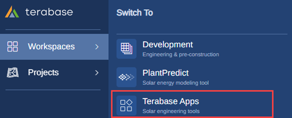
Voltage Pro is bundled with Plant Predict. Pro and Enterprise tier licenses of Plant Predict have full access to Voltage Pro while all other license tiers have read only access. The application may be accessed from within the Plant Predict left navigation panel as follow: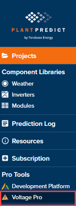
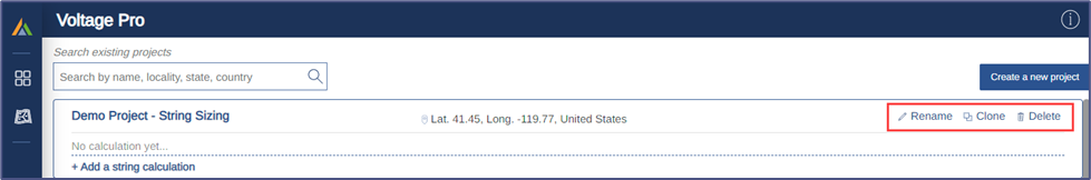
2.2 Creating, Editing and Cloning a Project
Within Voltage Pro, a Project must be created before a string sizing calculation can be performed. To create a new Project, click the Create a New Project button and enter the project name, latitude, and longitude.
Create a new project
Project options
2.3 Creating, Editing and Cloning String Sizing Calculations
Once a Project has been created, a new String Sizing Calculation may be created within the Project by clicking the + Add a string calculation button:
Add a string calculation
2.4 Selecting Weather Data
Weather data is critical to simulation-based string sizing calculations and Voltage Pro makes it easy to pull in weather-related data due to its integration with Plant Predict. From within the calculation page, click the Update button associated with Weather data: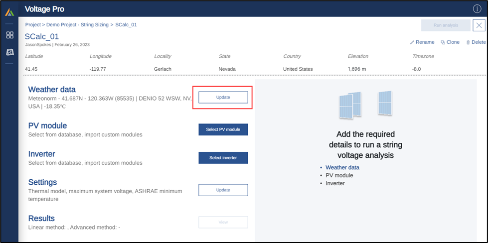
Selecting weather data
Meteorological data
The Meteorological data tab allows the user to select the weather data file that will be used in the simulation-based calculation. All weather data files accessible to the user from Plant Predict are also accessible within Voltage Pro. The My weather files toggle button limits the weather datasets to only those that are owned by the user within Plant Predict. New weather data files must be added within Plant Predict before they can be loaded into Voltage Pro. Note that Plant Predict supports single year, partial year, and multi-year data as well as hourly and sub-hourly data. Once selected, basic information about the weather dataset selected will be displayed in the input panel.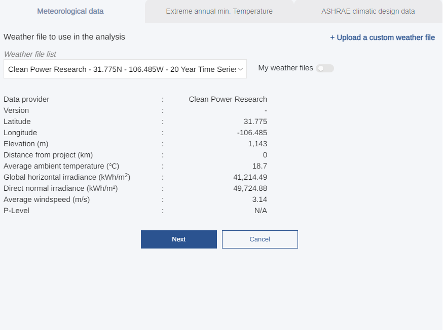
Meteorological data tab
Extreme annual min. Temperature
The Extreme annual min. Temperature tab allows the user to view the range of months and years of the dataset selected within the Meteorological data tab. It also allows users to deselect or remove certain years from the meteorological data to be used in the simulation. This can be done by deselecting checkbox next to the year and is often done to remove partial years of data. Finally, the average extreme annual min. temperature from the selected years of the meteorological dataset is displayed. This temperature will be used in the calculation of the certain safety factors.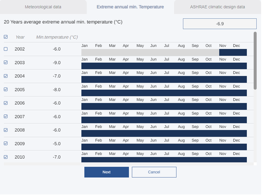
Extreme annual min. Temperature tab
ASHRAE climactic design data
By default, temperature data from the ASHRAE weather station closest to the Project site is pulled into the calculation. Specifically, the extreme annual mean minimum dry bulb temperature is used in both the Method 1 and Method 2 calculations and is displayed within the input panel.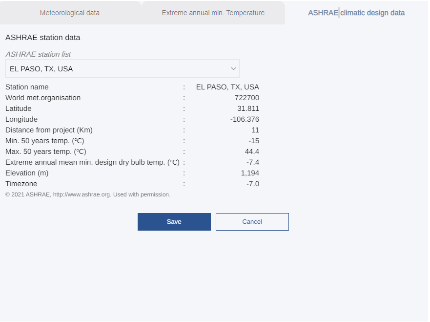
ASHRAE climatic design data tab
2.5 Selecting PV Module Data
Module data is critical to simulation-based string sizing calculations and Voltage Pro makes it easy to pull in module data due to its integration with Plant Predict. From within the calculation page, click the Select PV module button associated with PV module: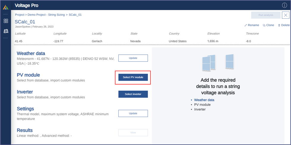
Select PV module
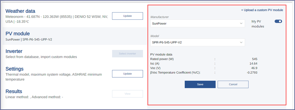
PV module tab
2.6 Selecting Inverter Data
Inverter data is used within Voltage Pro to set the maximum DC system voltage level (although this can be overridden in the calculation Settings). The inverter selected will be used within the Plant Predict simulation but will not impact the open circuit voltage calculation of the PV module. From within the calculation page, click the Select inverter button associated with Inverter: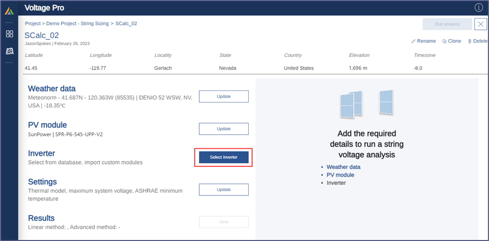
Select inverter
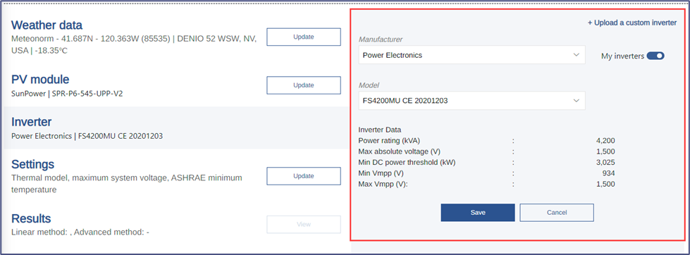
Inverter tab
2.7 Modifying Calculation Settings
Several calculation settings may be modified as follows:Thermal Model
Module voltage is heavily influenced by cell temperature. The cell thermal model within the Method 2 simulation may be selected as either the Heat Balance Model (default) or the Sandia Thermal Model (optional). The Heat Balance Model is the default cell thermal model for all Plant Predict energy predictions.Conductive and Convective Coefficients
The conductive and convective coefficients used by the cell thermal models may be adjusted. These are used within the Method 2 simulation for their respective thermal model. If the Heat Balance Thermal Model is selected, the Sandia coefficients will not impact the calculations in any way and vice-versa.Maximum System Voltage
By default, the maximum inverter voltage is used within the Method 1 and Method 2 calculations. However, this may be overridden where other DC components have a lower maximum DC voltage limitation or where additional conservatism is desired.ASHRAE extreme annual mean minimum dry bulb temperature
By default, the ASHRAE extreme annual mean minimum dry bulb temperature from the nearest ASHRAE station to the project site is loaded. This may be overridden by the user if desired.2.8 Running the Analysis
Once all inputs have been entered, enter the Results tab click the Run analysis button to begin the calculation.
Run the analysis

Analysis in progress
2.9 Accessing Results
Once the calculation has finished, the Results Summary tab will be displayed providing both Method 1 (Simplified Linear Method) and Method 2 (Plant Predict Advanced Simulation):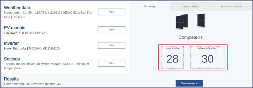
Summary results
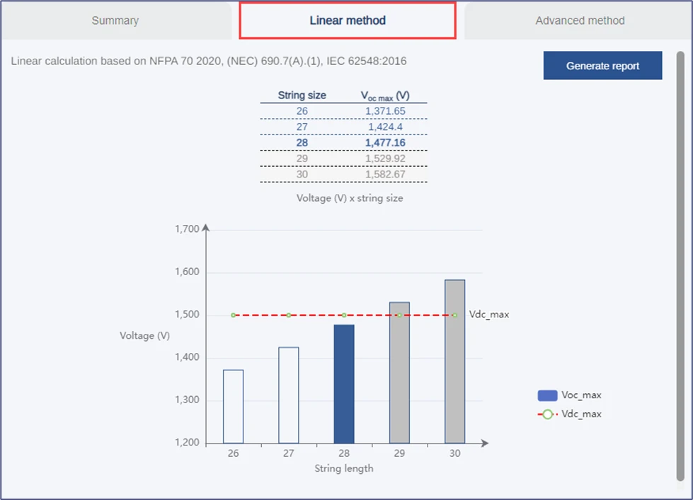
Linear method results
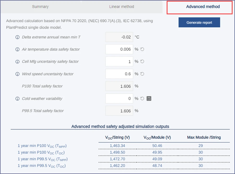
Advanced method results
2.10 Safety Factors
There are four (4) safety factors displayed on the Advanced Method tab which can be adjusted by the user to add or reduce the safety margin applied to the VOC simulation outputs. These are calculated automatically but can be adjusted after the simulation has run since the safety factors are applied to the results of the simulation. Positive safety factors add safety margin to the simulation results while negative safety factors reduce safety margin from the simulation results. A more detailed description of the purpose of each safety factor as well as the mathematical derivations of each safety factor is provided in Chapter 3 (Models & Algorithms).P100 Total Safety Factor
The following safety factors are added together and applied to the P100 simulation results (at TMPP and TOC):- Air Temperature Data Safety Factor
- Cell Mfg. Uncertainty Safety Factor
- Wind Speed Uncertainty Safety Factor
P99.5 Total Safety Factor
The following safety factors are added together and applied to the P99.5 simulation results (at TMPP and TOC):- Air Temperature Data Safety Factor
- Cell Mfg. Uncertainty Safety Factor
- Wind Speed Uncertainty Safety Factor
- Cold Weather Variability Safety Factor
2.11 Generating Reports
An output report can be generated by clicking the Generate Report button. The report will be automatically downloaded as a PDF file into the user’s default download folder. Each time the report is generated, the safety factors and safety adjusted simulation results will be updated to reflect the latest values entered within the Advanced Method tab. The report includes a date and time stamp to distinguish it from alternate versions (with different safety factors) created from the same calculation. The report is intended to document the primary inputs and outputs of the string sizing calculation and present the results across several calculation methods.2.12 Accessing the Prediction in Plant Predict
From within Plant Predict, the project created by Voltage Pro can be found by searching for the Voltage Pro project name and/or by filtering for projects of type StringSize:
PlantPredict project status
3 Models & Algorithms
3.1 Plant Predict Models & Algorithms
For more information on the underlying Plant Predict models & algorithms, please reference the following documentation: PlantPredict resource center3.2 Method 1 Calculation (Simplified Linear Approximation)
The Method 1 Calculation utilizes the traditional string sizing equation that has been prevalent in the solar PV industry for many years:
- It uses historical, extreme low temperature data coincident with module voltage characteristics at Standard Test Conditions (e.g., 1000W/m2) which are unlikely to be coincident in practice since historical low temperatures typically occur at night.
- It assumes the cell temperature is equal to the ambient temperature. However, the cell is expected to be warmer than ambient temperatures at high irradiances and warmer cell temperatures suppress VOC.
3.3 Method 2 Calculation (Plant Predict Advanced Simulation)
The Method 2 Calculation leverages the module model within Plant Predict to compute the open circuit voltage (VOC) of the module and string at each time step of an energy prediction. For more information on the Plant Predict module model, please refer to the Plant Predict Models & Algorithms documentation. It is recommended as industry best-practice to use hourly, historical, time-series weather data that spans approximately 20 years. This better incorporates outlier weather conditions that may not be present in single year or TMY datasets. For a 20-year dataset (at hourly time intervals), the open circuit voltage for over 175,000 hours would be computed. The module model also incorporates a cell thermal model and uses the effective plane of array (POA) irradiance and module characteristics to determine the current-voltage (IV) characteristics of the module and string (including VOC) at each time step of the prediction. Because cell temperature is so critical influential on VOC, two cell thermal models are available within Voltage Pro/Plant Predict as follows:- Heat Balance Cell Thermal Model – this is the default model within Voltage Pro/Plant Predict and is the same thermal model used by PVsyst.
- Sandia Cell Thermal Model – This is an optional cell thermal model developed by Sandia National Labs.
- VOC-MPP represents the open circuit voltage at the instant a string is open circuited from an MPP operating point (before the cells have warmed up to OC conditions).
- VOC-OC represents the open circuit voltage of a string that has been at an OC condition for at least several minutes (allowing the cells to warm to a steady-state temperature).
3.4 Default System Configuration
Voltage Pro does not require the input of many system configuration inputs to simplify the use of the application. However, this information is needed to successfully run the prediction in Plant Predict and obtain the open circuit voltages. By default, Voltage Pro assumes a single axis tracking system configuration with low ground coverage ratio that is expected to result in conservatively high POA irradiances compared to alternative system configurations. The following system configuration is assumed for all Voltage Pro calculations: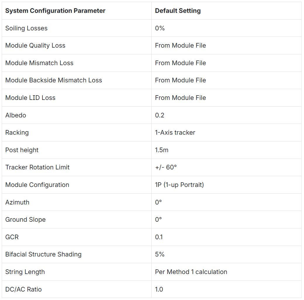
3.5 Determination of P100 and P99.5 Voltages
Voltage Pro calculates and reports P100 and P99.5 open-circuit voltages. The IEEE Journal of Photovoltaics research referenced in section 1.4 recommends using the P99.5 open-circuit voltage as a basis for String Sizing. These are derived as follows: P100 VOC represents the 100th percentile (or absolute maximum) VOC value computed in the n-year prediction. No computed VOC values were larger. **P99.5 VOC **represents the 99.5th percentile VOC value computed in the n-year prediction. Only 0.5% of computed VOC values were larger.3.6 Determination of Open Circuit Cell Temperature
Open circuit cell temperature is derived from the maximum power point (MPP) cell temperature using the following equation (which has been taken from the IEEE Journal of Photovoltaics research referenced in section 1.4):
3.7 Determination of Safety Factors
Safety factors are applied to the open circuit voltage simulation results to provide an additional safety margin. The following safety factors are considered within Voltage Pro:Air Temperature Data Safety Factor
The Air Temperature Data Safety Factor (SFATD) attempts to account for the fact that satellite-derived air temperature data is used in the VOC simulations and may be biased. This safety factor uses a comparison between long-term ground measured temperature data and satellite temperature data. The comparison is made between the extreme annual mean minimum dry bulb temperatures of each source. The safety factor is calculated as follows:
- Where CPR / SolarAnywhere weather data is used, ΔTATD has been pre-calculated for the entire Earth and is automatically pulled into the Voltage Pro calculation based on the project latitude and longitude. CPR prepared a World ΔTATD Map by calculating the difference between EAMMTGround and EAMMTSatellite for 8,500+ ASHRAE ground measurement stations around the world and then bilinearly interpolating the results between all 8,500+ points.
The map of ASHRAE EAMMTGround measurement points is as follows:
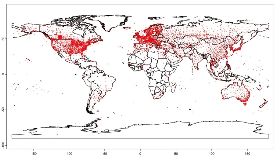
ASHRAE EAMMTGround measurement points map
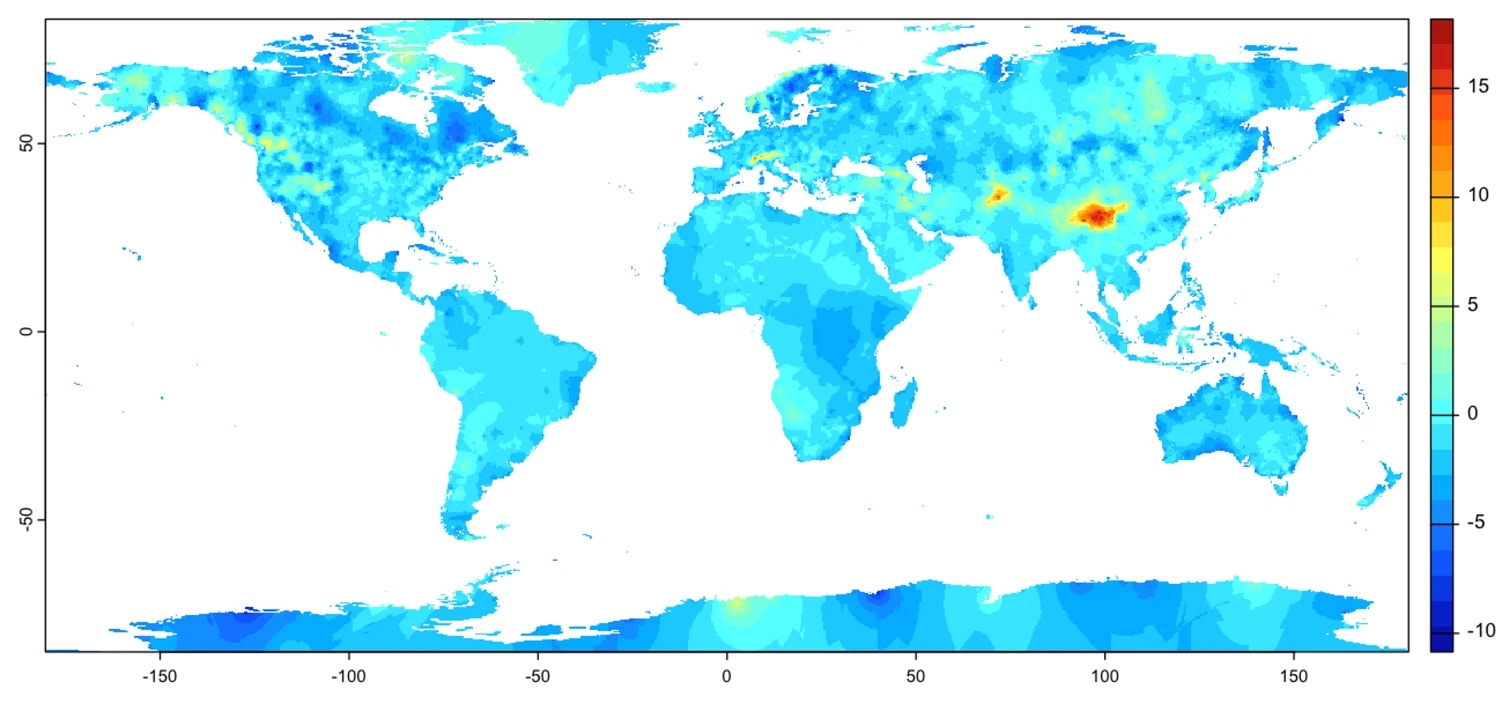
Clean Power Research World ΔTATD Map
- Where the weather data source is not CPR / SolarAnywhere, ΔTATD is automatically calculated as the EAMMTGround (from the nearest ASHRAE weather station) minus the EAMMTSatellite (from the project weather dataset loaded into the Voltage Pro calculation). This is a reasonable approach where the project location (and satellite weather dataset) is near the ground measurement station (ASHRAE station) but may lose accuracy as the distance between these two increases.
Cell Manufacturing Uncertainty Safety Factor
The Cell Manufacturing Uncertainty Safety Factor attempts to account for slight deviations in cell characteristics between different modules of the same rating. It is well understood that manufacturing tolerances allow for some deviation between cells. The default Cell Manufacturing Uncertainty Safety Factor = 1.0% for all module types (as suggested by the IEEE Journal of Photovoltaics research referenced in section 1.4). This can be overridden by the user.+Wind Speed Uncertainty Safety Factor
Wind has a cooling effect on cell temperature and can cause increased open circuit voltages as a result. The effect of wind speed in the weather data can be incorporated in the cell thermal model (through the setting of the convective coefficient). However, the accuracy, coincidence with ambient temperature and irradiance, and edge effects at the outer perimeter of the array lead to additional uncertainty. The default **Wind Speed Safety Factor = 0.6% **for all module types (as suggested by the IEEE Journal of Photovoltaics research referenced in section 1.4). This can be overridden by the user.Diode Ideality Factor Uncertainty Safety Factor
A Diode Ideality Safety Factor (as suggested by the IEEE Journal of Photovoltaics research referenced in section 1.4) is intended to account for simulations where the diode ideality factor is not known and a typical ideality factor is used in its place. This is common when only datasheet information is known. However, the Plant Predict module database comprises diode ideality factors provided by the manufacturer (generally via PAN file) and therefore this safety factor is not automatically applied to Voltage Pro calculations. It is, however, documented in the calculation report as 0% for completeness.Bifacial Gain Voltage Rise Safety Factor
The impact of bifacial gain on open circuit voltage (VOC) is inherently built into the Plant Predict prediction and thus, the Voltage Pro results already include the impact of bifacial gain. As a result, an additional safety factor is not automatically included (as is suggested by the IEEE Journal of Photovoltaics research referenced in section 1.4). It is, however, documented in the calculation report as 0% for completeness.Cold Weather Variability Safety Factor
The Cold Weather Variability Safety Factor (SFCWV) attempts to account for the fact that some locations have larger extreme minimum temperature fluctuations than others. This safety factor is proposed as an optional safety factor to be applied to the P99.5 results only by the IEEE Journal of Photovoltaics research referenced in section 1.4. As such, Voltage Pro uses SFCWV = 0% by default but will automatically calculate and apply this safety factor if desired by the user. The safety factor is calculated as follows: