> ## Documentation Index
> Fetch the complete documentation index at: https://docs.plantpredict.com/llms.txt
> Use this file to discover all available pages before exploring further.
# Terrain Pro User Guide
September 08, 2025
## **Overview**
Terrain Pro is a cloud-based application that calculates earthwork quantities and supports rack profile optimization for solar array layouts generated by **Terabase Design Pro** or directly imported from **CAD (DXF)** and **Excel (XLSX)** or **CSV**.
The application supports:
* Earthwork quantities (cut/fill volumes, disturbed area, max cut/fill depths).
* Heatmaps (cut/fill, original/finish surface).
* Finish grade point file.
* Top-of-pile elevations and reveals.
* Tracker profiles.
* Reports and comparisons.
## **Integration with Design Pro**
Terrain Pro is tightly integrated with Terabase **Design Pro** and is accessible with a Terabase Plant Predict Pro license. From a Design Pro project, you can launch Terrain Pro directly from the scenario table, which automatically passes pile coordinates and tracker metadata.
## **Standalone use**
Starting with v12.3.0, Terrain Pro can import **DXF** files, and starting with v12.4.0 it can also import **XLSX** files (e.g., PVCase BOM) and CSV file. These imports allow Terrain Pro to analyze pile layouts and elevation data without going through a Design Pro automatic layout, but importing array layout data generated from different sources.
## **What’s new Sep 4, 2025**
* **New 2D/3D Viewer** (replaces ArcGIS scene view) → \[\[Link: Use the Viewer]]
* **Wind Exposure logic** with **Pile icon** showing the assigned **Pile Type** → \[\[Link: Wind Exposure (concept)]], \[\[Link: Review & Override Pile Types]]
* **Export to CAD** (layered DXF with CRS handling) → \[\[Link: Export to CAD]]
***
# **Accessing Terrain Pro**
## **Path 1 — Integrated with Design Pro**
In **Design Pro** [**\[link\]**](https://platform.terabase.energy/homepage "https://platform.terabase.energy/homepage"), open your project and select your simulation.
1. In the scenario table, click the **Terrain Pro** icon.
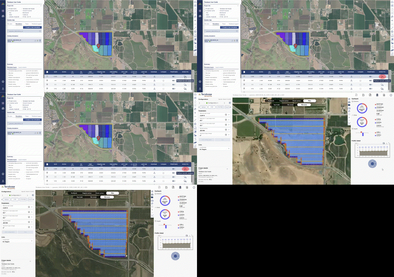 2. Design Pro sends pile coordinates and tracker metadata; Terrain Pro opens ready to run.
3. Elevation source for the DP layout is listed in the report (see **Appendix**).
**Best when:** your source of truth is Design Pro and you want one‑click terrain analysis.
## **Path 2 — Standalone application**
From the Pro tools page [\[link\]](https://platform.terabase.energy/tools "https://platform.terabase.energy/tools") click the Terrain Pro icon to open the standalone landing page.
2. Design Pro sends pile coordinates and tracker metadata; Terrain Pro opens ready to run.
3. Elevation source for the DP layout is listed in the report (see **Appendix**).
**Best when:** your source of truth is Design Pro and you want one‑click terrain analysis.
## **Path 2 — Standalone application**
From the Pro tools page [\[link\]](https://platform.terabase.energy/tools "https://platform.terabase.energy/tools") click the Terrain Pro icon to open the standalone landing page.
 In the Terrain Pro home page all the analysis created by the user and his company members are visible and sorted by creation date.
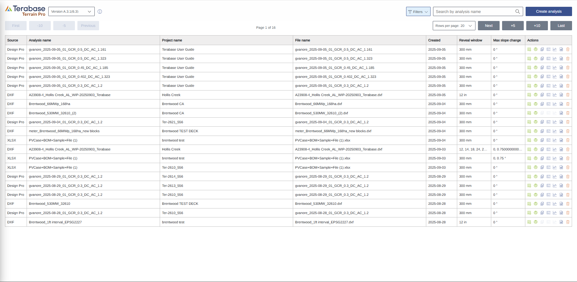 The column ***Source*** indicates the data source used to run the Terrain Pro analysis.
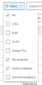
Using the filters it is possible visualize all the analyses or filter them by input data, or by Active and or Archived
Using the search input box it is also possible to search the analysis by name
The column ***Source*** indicates the data source used to run the Terrain Pro analysis.
Using the filters it is possible visualize all the analyses or filter them by input data, or by Active and or Archived
Using the search input box it is also possible to search the analysis by name
 ## Opening existing analysis
To access the Terrain Pro viewer/configuration page go to the **Actions** column and click on the “***Launch Terrain Pro viewer***” icon
## Opening existing analysis
To access the Terrain Pro viewer/configuration page go to the **Actions** column and click on the “***Launch Terrain Pro viewer***” icon
 ## **Create analysis**
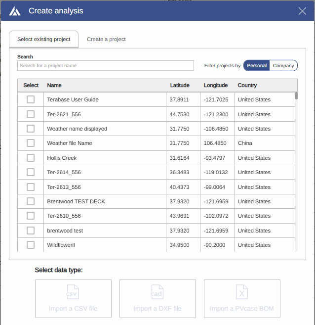
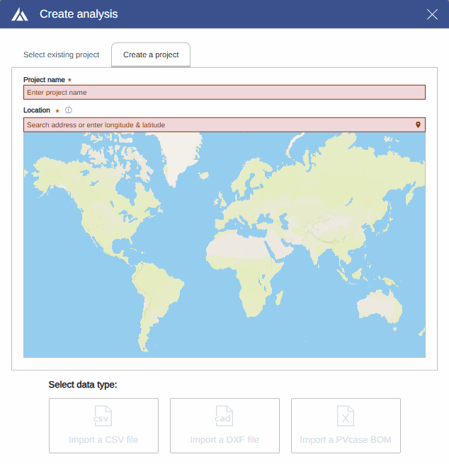
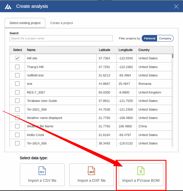
1. Click **Create Analysis** then either:
* Select an **existing project** and upload new data, or
* **Create a new project** and set its location.
## **Create analysis**
1. Click **Create Analysis** then either:
* Select an **existing project** and upload new data, or
* **Create a new project** and set its location.
 2. Choose which type of file to import
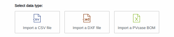 * **CSV (v12.4.0+)** — Piles coordinates, elevations and rack Id
* **DXF (v12.3.0+)** — CAD layout & topographic polylines
* **XLSX (v12.4.0+)** — Piles & elevations + rack config (PVCase BOM supported)
**Best when:** design originates in CAD/PVCase or from external partners.
## **Import CSV file**
1. Click **Create analysis**. After selecting an existing project or creating a new one, click on Import CSV and choose your file:
* **CSV (v12.4.0+)** — Piles coordinates, elevations and rack Id
* **DXF (v12.3.0+)** — CAD layout & topographic polylines
* **XLSX (v12.4.0+)** — Piles & elevations + rack config (PVCase BOM supported)
**Best when:** design originates in CAD/PVCase or from external partners.
## **Import CSV file**
1. Click **Create analysis**. After selecting an existing project or creating a new one, click on Import CSV and choose your file:
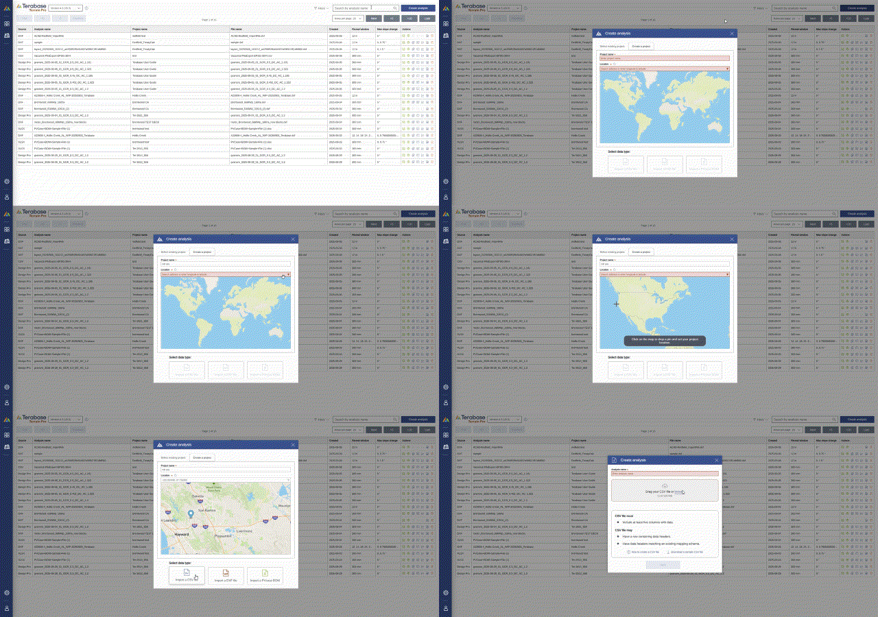 2. Once the file is selected, Terrain Pro analyzes it and checks whether the required fields are present.
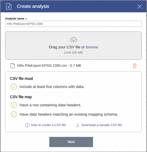 3. If the minimum requirements are satisfied, the **Next** button becomes active. You can then proceed to the next page, where you can:
* Specify the data unit (meters or feet).
* Provide the coordinate system EPSG code.
* Verify that the file header matches any existing configuration previously imported and validated.
3. If the minimum requirements are satisfied, the **Next** button becomes active. You can then proceed to the next page, where you can:
* Specify the data unit (meters or feet).
* Provide the coordinate system EPSG code.
* Verify that the file header matches any existing configuration previously imported and validated.
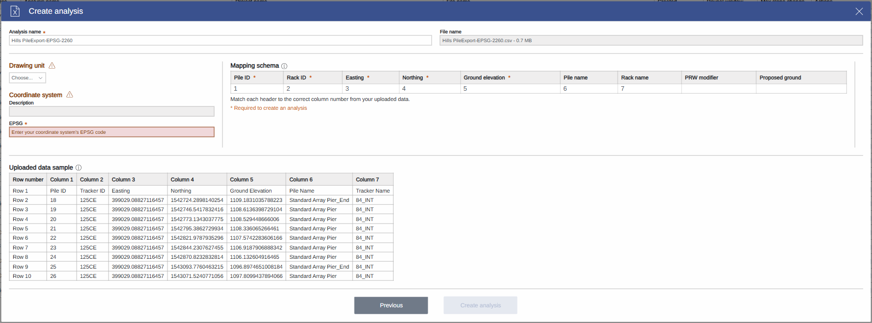 4. If the dataset is missing a header, or if the header does not match any existing schema, you can manually map the available fields to the required data fields (such as **Pile ID**, **Rack ID**, **Easting**, **Northing**, **Ground elevation**).
## **Import DXF file**
1. Click **Create Analysis**, then choose **Import DXF** and select your file.
4. If the dataset is missing a header, or if the header does not match any existing schema, you can manually map the available fields to the required data fields (such as **Pile ID**, **Rack ID**, **Easting**, **Northing**, **Ground elevation**).
## **Import DXF file**
1. Click **Create Analysis**, then choose **Import DXF** and select your file.
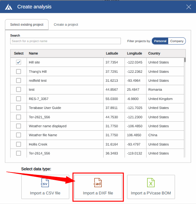 2. Once uploaded, Terrain Pro validates the file to ensure it meets the required conditions:
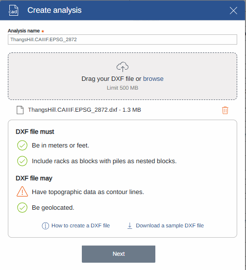 * **Unit compatibility**: The file must use meters (SI) or feet (Imperial).
* **Block structure**: Racks must be represented as CAD blocks, with piles nested as sub-blocks. Terrain Pro automatically detects common names like *pile*, *post*, *column*, or *pier*, but you can remap custom names if needed. Blocks are read accurately even if rotated, scaled, or mirrored.
* **Elevation data**: Topographic data must be represented as polylines with valid elevation values, typically as `LWPOLYLINE`. These are used to build the Triangular Irregular Network (TIN) that defines the surface. Only relevant elevation layers are processed; non-terrain data such as overhead lines is ignored.
* **Coordinate system (EPSG code)**: If provided in the DXF, Terrain Pro uses it to geolocate the project and overlay heat maps, contours, and data correctly. If no EPSG is present, the analysis still runs, but geolocation may be less accurate.
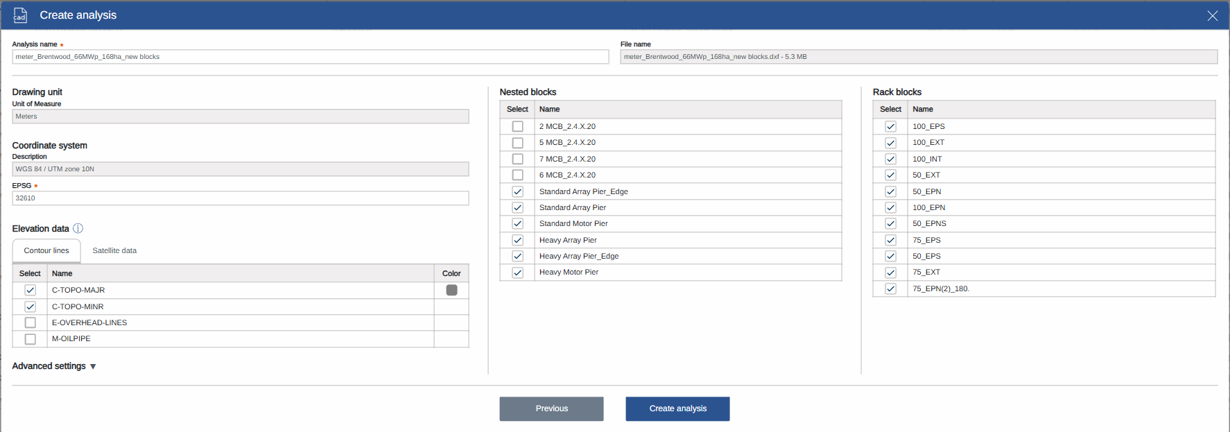
3. After validation, the **Next** button becomes active. You can then select which elevation layers to use for generating the TIN and confirm which blocks represent piles and racks before proceeding to the analysis.
* **Unit compatibility**: The file must use meters (SI) or feet (Imperial).
* **Block structure**: Racks must be represented as CAD blocks, with piles nested as sub-blocks. Terrain Pro automatically detects common names like *pile*, *post*, *column*, or *pier*, but you can remap custom names if needed. Blocks are read accurately even if rotated, scaled, or mirrored.
* **Elevation data**: Topographic data must be represented as polylines with valid elevation values, typically as `LWPOLYLINE`. These are used to build the Triangular Irregular Network (TIN) that defines the surface. Only relevant elevation layers are processed; non-terrain data such as overhead lines is ignored.
* **Coordinate system (EPSG code)**: If provided in the DXF, Terrain Pro uses it to geolocate the project and overlay heat maps, contours, and data correctly. If no EPSG is present, the analysis still runs, but geolocation may be less accurate.
3. After validation, the **Next** button becomes active. You can then select which elevation layers to use for generating the TIN and confirm which blocks represent piles and racks before proceeding to the analysis.
 ## **Use Satellite elevation data (DXF only)**
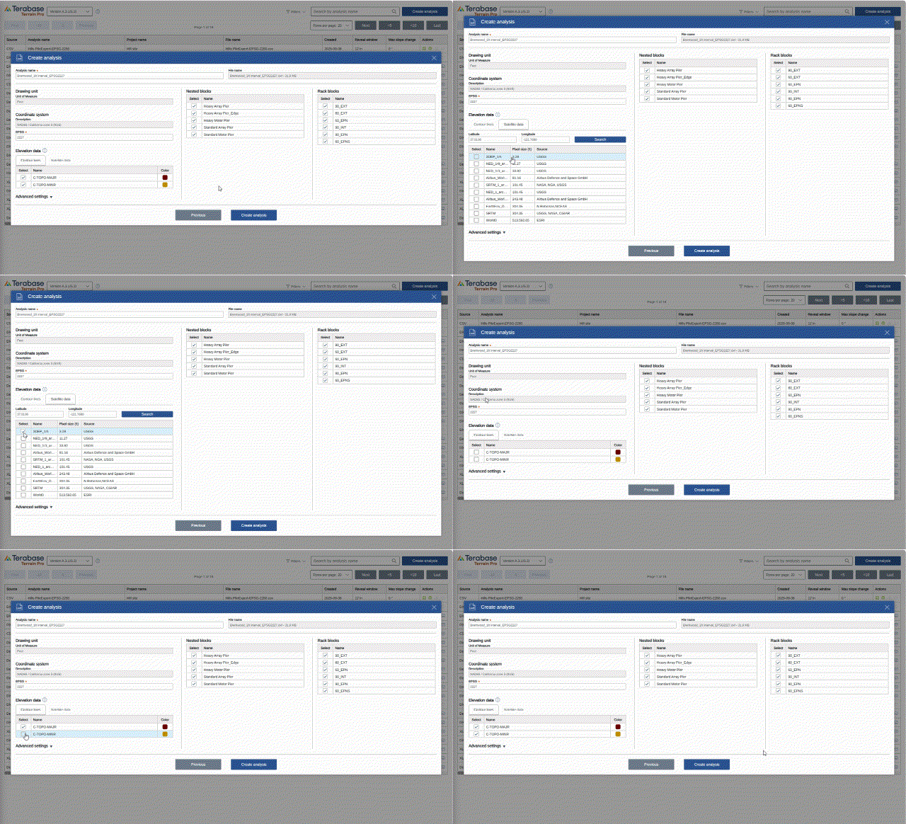
In the **DXF validation** screen you can replace (or supply) elevation data using **Satellite data** from the datasets listed in the [Appendix](https://terabase.atlassian.net/wiki/spaces/PPKB/pages/2488238088 "https://terabase.atlassian.net/wiki/spaces/PPKB/pages/2488238088").
1. **Open the Satellite data tab**
## **Use Satellite elevation data (DXF only)**
In the **DXF validation** screen you can replace (or supply) elevation data using **Satellite data** from the datasets listed in the [Appendix](https://terabase.atlassian.net/wiki/spaces/PPKB/pages/2488238088 "https://terabase.atlassian.net/wiki/spaces/PPKB/pages/2488238088").
1. **Open the Satellite data tab**
 2. **Choose your scenario**
* **Replace DXF elevations**: If your DXF already contains elevation polylines but you prefer DEM/satellite data, select **Use satellite data instead of DXF polylines**.
* **No elevation in DXF**: If the DXF has **no** elevation polylines, select **Use satellite data** to build the surface.
3. **Geolocate the project**
* If the DXF includes a valid **EPSG** code, Terrain Pro will locate the project automatically.
* If **no EPSG** is present, enter the **latitude and longitude** of a known point within the site to locate the project and fetch available elevation datasets for that area.
4. **Select an elevation dataset**
* Terrain Pro lists the **available DEM/satellite sources** for the project location (see **Appendix: Elevation Data Sources**).
* Choose the dataset that best fits your needs. In parts of the **United States**, coverage with **up to \~1 m accuracy** is available.
## **Import XLSX file**
1. Click **Create Analysis**, then choose **Import XLSX** and select your file.
2. **Choose your scenario**
* **Replace DXF elevations**: If your DXF already contains elevation polylines but you prefer DEM/satellite data, select **Use satellite data instead of DXF polylines**.
* **No elevation in DXF**: If the DXF has **no** elevation polylines, select **Use satellite data** to build the surface.
3. **Geolocate the project**
* If the DXF includes a valid **EPSG** code, Terrain Pro will locate the project automatically.
* If **no EPSG** is present, enter the **latitude and longitude** of a known point within the site to locate the project and fetch available elevation datasets for that area.
4. **Select an elevation dataset**
* Terrain Pro lists the **available DEM/satellite sources** for the project location (see **Appendix: Elevation Data Sources**).
* Choose the dataset that best fits your needs. In parts of the **United States**, coverage with **up to \~1 m accuracy** is available.
## **Import XLSX file**
1. Click **Create Analysis**, then choose **Import XLSX** and select your file.
 2. After upload, Terrain Pro analyzes the workbook and validates the required content:
* A **Piles** table with at minimum **Pile ID**, **Easting**, **Northing**, and **Ground elevation**.
* (Optional) **Racks** / configuration tables and layout/module metadata.
* **PVCase BOM** files are recognized; detected sheets and columns are auto‑mapped when possible.
2. After upload, Terrain Pro analyzes the workbook and validates the required content:
* A **Piles** table with at minimum **Pile ID**, **Easting**, **Northing**, and **Ground elevation**.
* (Optional) **Racks** / configuration tables and layout/module metadata.
* **PVCase BOM** files are recognized; detected sheets and columns are auto‑mapped when possible.
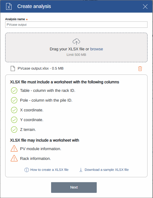 1. If the minimum requirements are satisfied, the **Next** button becomes active. On the next screen you can:
1. Specify the distance **units** (meters or feet).
2. Provide the **coordinate system (EPSG code)** for geolocation (recommended).
3. Select the area for which import the data (if the dataset is divided in areas)
1. If the minimum requirements are satisfied, the **Next** button becomes active. On the next screen you can:
1. Specify the distance **units** (meters or feet).
2. Provide the **coordinate system (EPSG code)** for geolocation (recommended).
3. Select the area for which import the data (if the dataset is divided in areas)
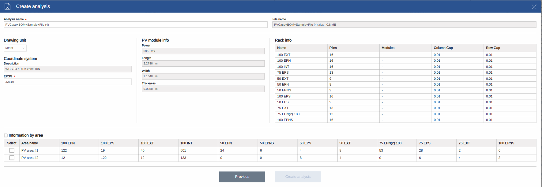 For template requirements and tips (including exporting a compatible **PVCase** BOM), see **Create Excel file compatible with Terrain Pro**: [Create Excel file compatible with Terrain Pro](https://terabase.atlassian.net/servicedesk/customer/kb/view/1985347587 "https://terabase.atlassian.net/servicedesk/customer/kb/view/1985347587")
## **Configurations**
By opening the input parameters containers, the user can add new [parameters](https://terabase.atlassian.net/wiki/spaces/PPKB/pages/2489188370 "https://terabase.atlassian.net/wiki/spaces/PPKB/pages/2489188370") and the application will automatically create a new configuration. More than one parameter can be changed to customize the configuration before hitting the button run to perform the terrain analysis.
## **Predefined rack configuration parameters**
In Terrain Pro's configuration page, a banner has been added above the input parameters allowing the users to chose preselect input parameters for their configurations.
For template requirements and tips (including exporting a compatible **PVCase** BOM), see **Create Excel file compatible with Terrain Pro**: [Create Excel file compatible with Terrain Pro](https://terabase.atlassian.net/servicedesk/customer/kb/view/1985347587 "https://terabase.atlassian.net/servicedesk/customer/kb/view/1985347587")
## **Configurations**
By opening the input parameters containers, the user can add new [parameters](https://terabase.atlassian.net/wiki/spaces/PPKB/pages/2489188370 "https://terabase.atlassian.net/wiki/spaces/PPKB/pages/2489188370") and the application will automatically create a new configuration. More than one parameter can be changed to customize the configuration before hitting the button run to perform the terrain analysis.
## **Predefined rack configuration parameters**
In Terrain Pro's configuration page, a banner has been added above the input parameters allowing the users to chose preselect input parameters for their configurations.
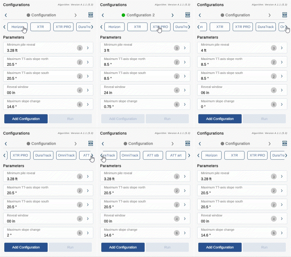 The details of the available input parameters are:
 ATT stands for **A**ll **T**errain **T**racker
## **Visualizing the input/output layer**
Once a configuration is completed, the application will show the pile assignment based on the wind exposure analysis performed on the layout.
ATT stands for **A**ll **T**errain **T**racker
## **Visualizing the input/output layer**
Once a configuration is completed, the application will show the pile assignment based on the wind exposure analysis performed on the layout.
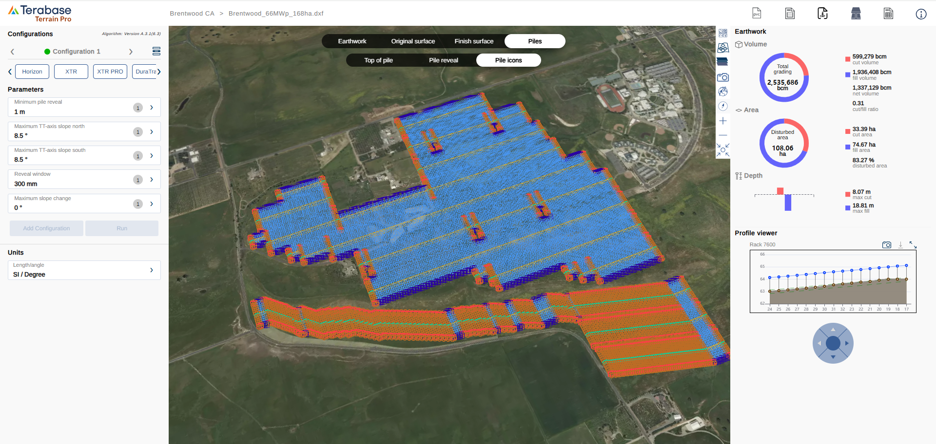 The user can navigate the earthwork heat map, the cut and fill map, the original and finish grade heat map and the pile’s elevation and reveal by the horizontal toolbar on the top of the map in the center of the screen.
## **Earthwork outputs and tracker profile**
The earthwork outputs are calculated at every run and are visible on the right menu on the screen.\
The tracker profile preview is available on the bottom of the right menu and can be expanded to full screen.\
The tracker profile snapshot and pile data can be downloaded both from the preview and form the expanded tracker view.
## **Configuration’s list and comparison**
To compare different configuration, the user can open the configuration list menu and select up to four configuration to compare:
## **Outputs**
For every run configuration, Terrain Pro delivers the following outputs:
* Earthwork heat map
* Earthwork cut/fill map
* Original surface heat map
* Finish surface heat map
* Top of the pile elevation map
* Pile reveal window map
* Pile type based on rack wind exposure
* Earthwork cut and fill volume quantities
* Earthwork cut and fill area quantities
* Max cut and max fill depth
* Tracker profile
* Terrain analysis report
* Terrain analysis comparison report
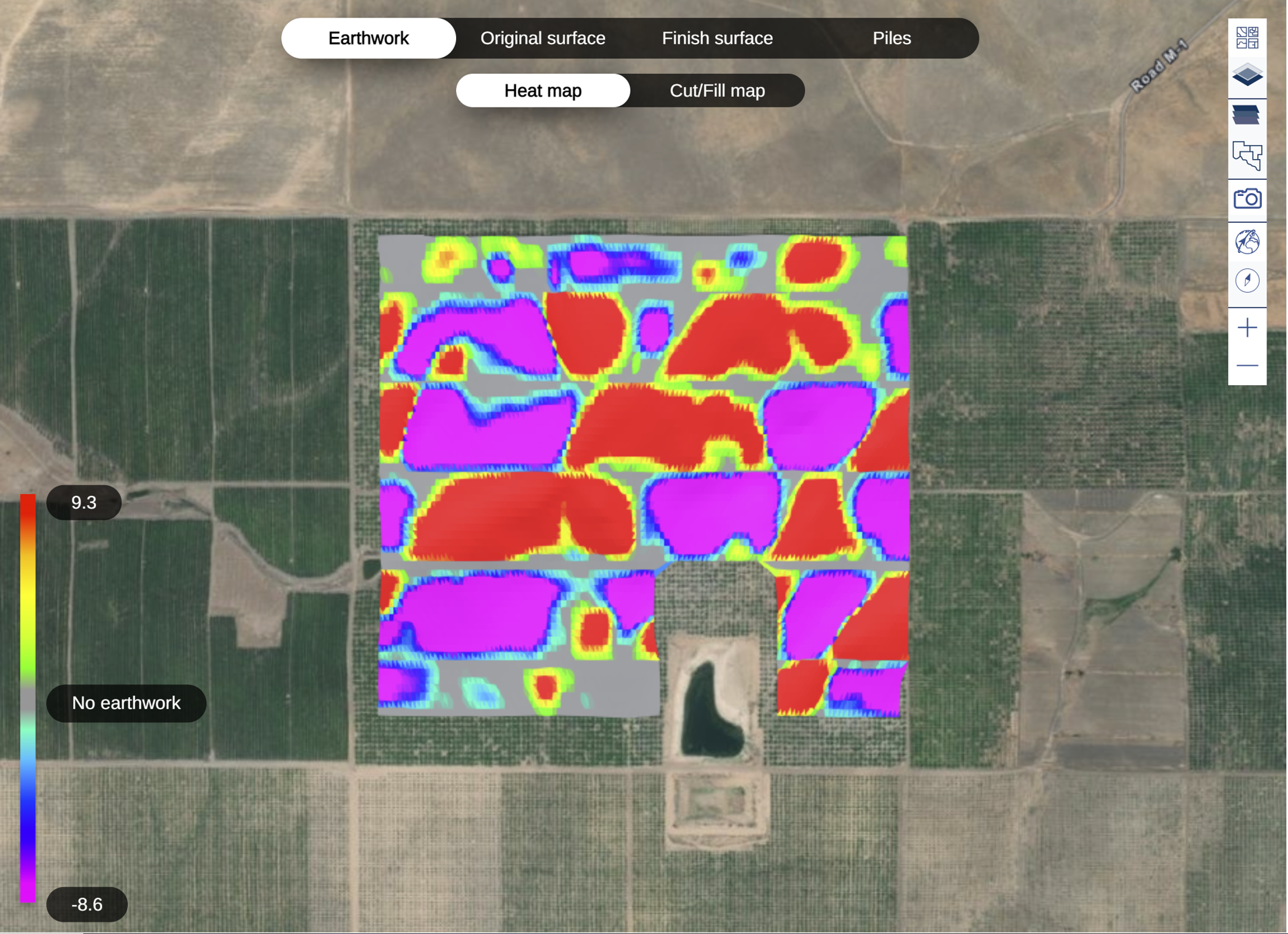
## **Earthwork heat map**
The earthwork heat map represent on the screen the area where cut and fill is required.\
The cut and fill area are represented using a gradient scale. The area with no earthwork are represented in gray.
The user can navigate the earthwork heat map, the cut and fill map, the original and finish grade heat map and the pile’s elevation and reveal by the horizontal toolbar on the top of the map in the center of the screen.
## **Earthwork outputs and tracker profile**
The earthwork outputs are calculated at every run and are visible on the right menu on the screen.\
The tracker profile preview is available on the bottom of the right menu and can be expanded to full screen.\
The tracker profile snapshot and pile data can be downloaded both from the preview and form the expanded tracker view.
## **Configuration’s list and comparison**
To compare different configuration, the user can open the configuration list menu and select up to four configuration to compare:
## **Outputs**
For every run configuration, Terrain Pro delivers the following outputs:
* Earthwork heat map
* Earthwork cut/fill map
* Original surface heat map
* Finish surface heat map
* Top of the pile elevation map
* Pile reveal window map
* Pile type based on rack wind exposure
* Earthwork cut and fill volume quantities
* Earthwork cut and fill area quantities
* Max cut and max fill depth
* Tracker profile
* Terrain analysis report
* Terrain analysis comparison report
## **Earthwork heat map**
The earthwork heat map represent on the screen the area where cut and fill is required.\
The cut and fill area are represented using a gradient scale. The area with no earthwork are represented in gray.
 ## **Earthwork cut and fill map**
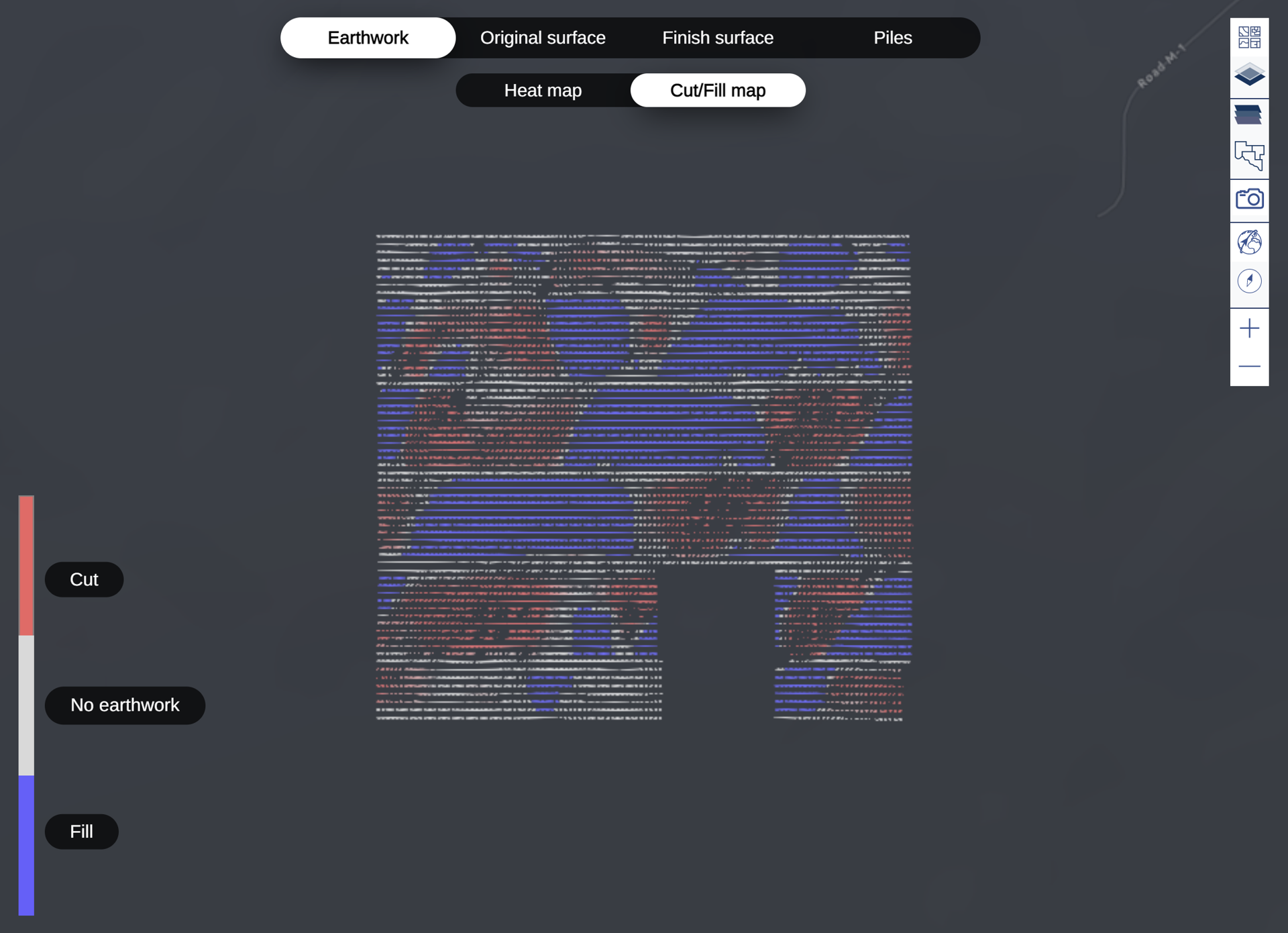
The earthwork cu/fill map shows the area where cut and fill is required, without showing the magnitude of the grading.
## **Earthwork cut and fill map**
The earthwork cu/fill map shows the area where cut and fill is required, without showing the magnitude of the grading.
 ## **Original and Finish surface heat map**
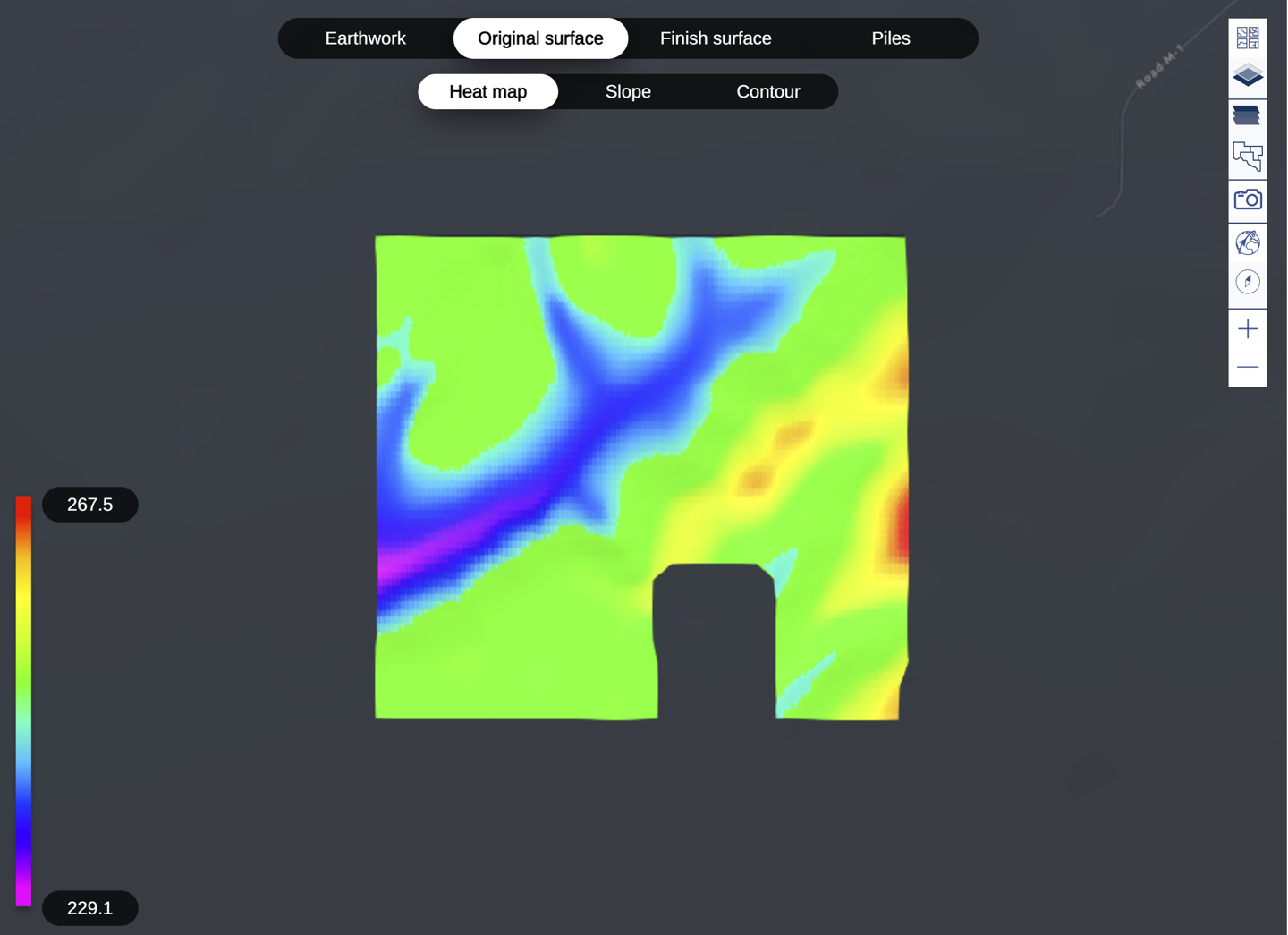
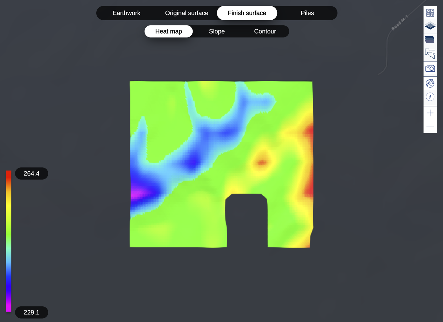
The original and finish surface heat map represent the elevation of the original surface extracted from the Design Pro application and the finish surface calculated by Terrain Pro.
## **Original and Finish surface heat map**
The original and finish surface heat map represent the elevation of the original surface extracted from the Design Pro application and the finish surface calculated by Terrain Pro.
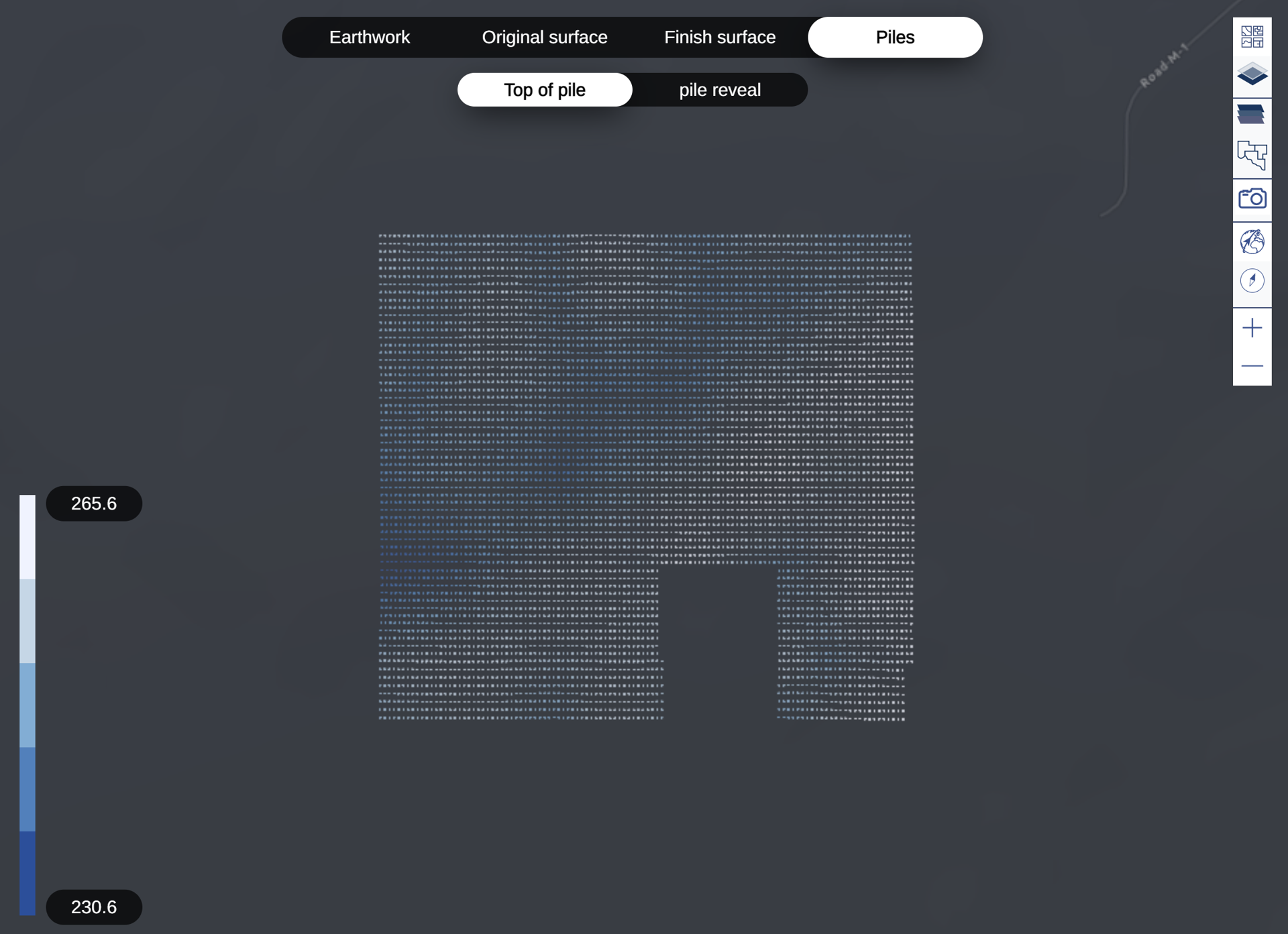
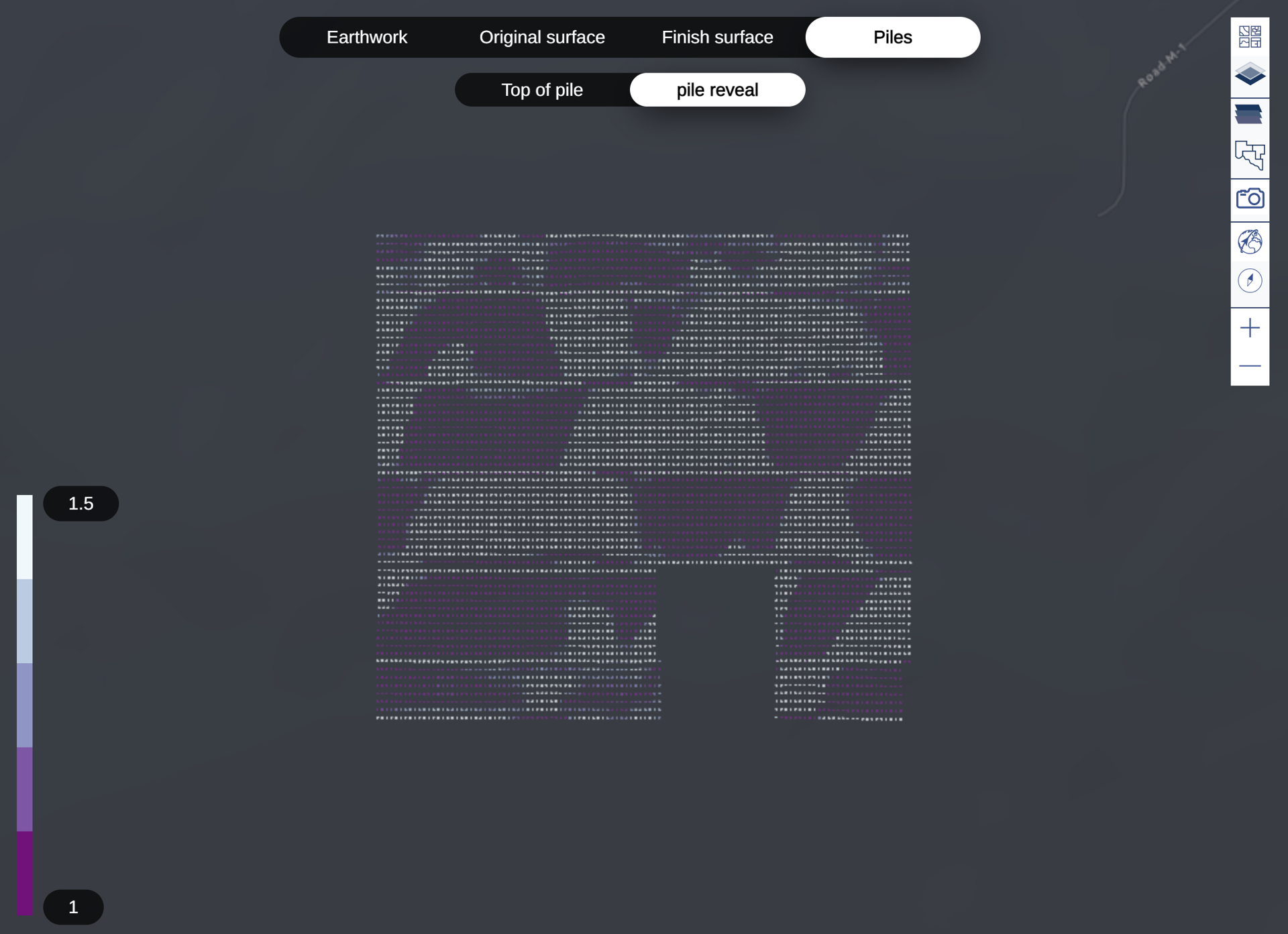
 ## **Top of pile elevation and pile reveal map**
The top of pile elevation and pile reveal map represent respectively the elevation above the finish surface of the top of the piles, and the reveal window value of every pile above the finish surface.
## **Top of pile elevation and pile reveal map**
The top of pile elevation and pile reveal map represent respectively the elevation above the finish surface of the top of the piles, and the reveal window value of every pile above the finish surface.
 ## **Earthwork cut and fill volume quantities**
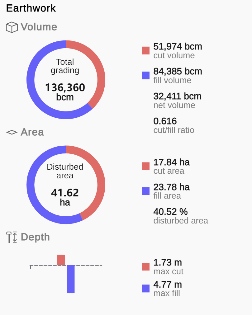
On the right menu, for every completed configuration are available the cut and fill volume in bcm (bank cubic meter) or bcy (bank cubic yard).
The net volume is the difference between the fill volume and cut volume
(Net volume) = (fill volume) - (cut volume)
The cut/fill ratio is the ratio between cut volume and fill volume.
The total grading represents the total grading required on the site summing the fill volume and the absolute value of the cut volume:
(Total grading) = (fill volume) + Abs(cut volume)
## **Earthwork cut and fill volume quantities**
On the right menu, for every completed configuration are available the cut and fill volume in bcm (bank cubic meter) or bcy (bank cubic yard).
The net volume is the difference between the fill volume and cut volume
(Net volume) = (fill volume) - (cut volume)
The cut/fill ratio is the ratio between cut volume and fill volume.
The total grading represents the total grading required on the site summing the fill volume and the absolute value of the cut volume:
(Total grading) = (fill volume) + Abs(cut volume)
 ## **Earthwork cut and fill area quantities**
Similarly in the area section, are available the cut area and fill area in ha or ac, depending on the project unit.
The disturbed area is sum of the cut and fill area:
(Disturbed area) = (cut area) + (fill area)
the percentage of disturbed area is the ratio between the disturbed area and the array area represented in percentage value.
## **Max cut and max fill depth**
The max cut and max fill indicate the max depth of cut and fill at the pile level.
## **Tracker profile**
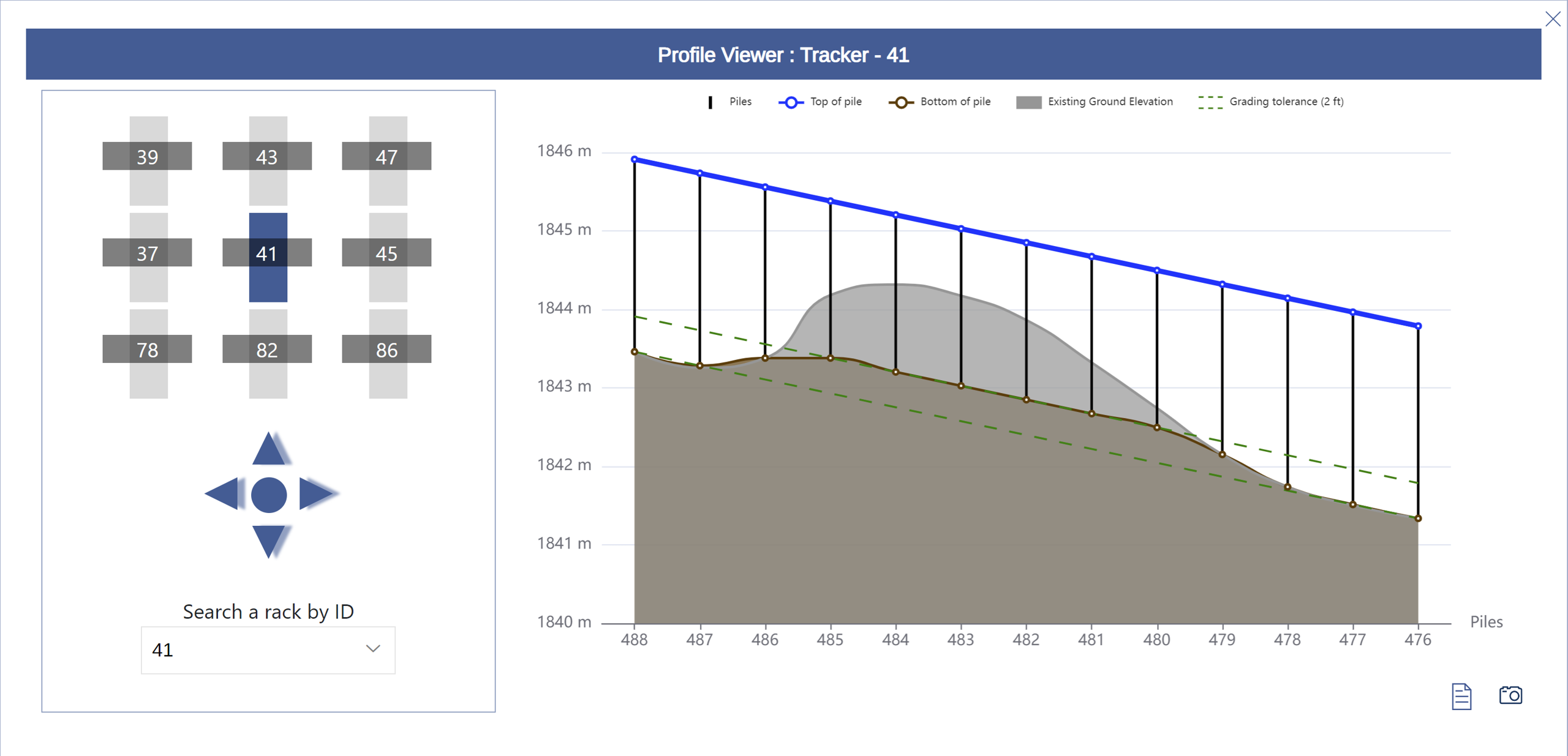
For every tracker is available the tracker profile as a miniature/preview in the right menu and by clicking on its expand icon, the profile will open in a popup window on the center of the browser.
The tracker profile shows the pile id, the existing grade and the finish grade, the top of the pile and the rack profile.\
The reveal window is also represented by two dashed green line.
The data is also available in numeric format to visualize and download.\
The tracker profile can be downloaded also as picture.
## **Earthwork cut and fill area quantities**
Similarly in the area section, are available the cut area and fill area in ha or ac, depending on the project unit.
The disturbed area is sum of the cut and fill area:
(Disturbed area) = (cut area) + (fill area)
the percentage of disturbed area is the ratio between the disturbed area and the array area represented in percentage value.
## **Max cut and max fill depth**
The max cut and max fill indicate the max depth of cut and fill at the pile level.
## **Tracker profile**
For every tracker is available the tracker profile as a miniature/preview in the right menu and by clicking on its expand icon, the profile will open in a popup window on the center of the browser.
The tracker profile shows the pile id, the existing grade and the finish grade, the top of the pile and the rack profile.\
The reveal window is also represented by two dashed green line.
The data is also available in numeric format to visualize and download.\
The tracker profile can be downloaded also as picture.
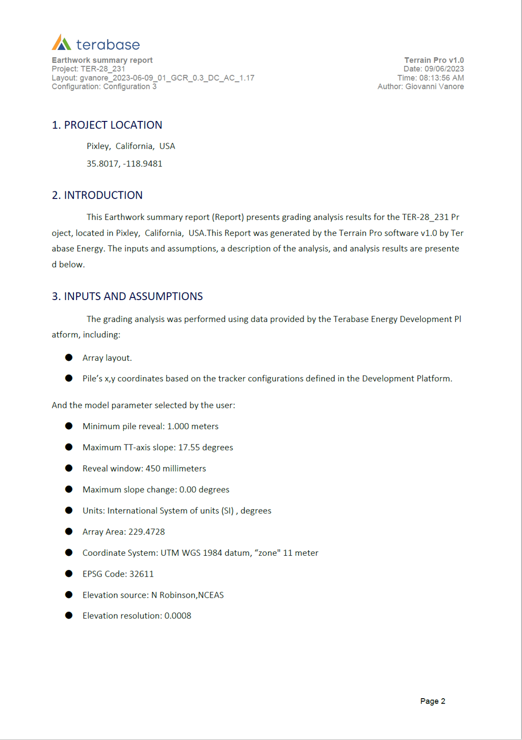
 ## **Terrain analysis report**
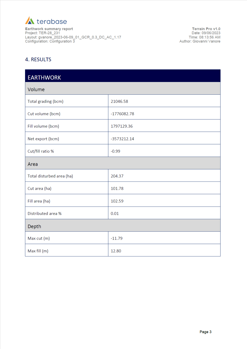
By clicking on the button “Generate report” an earthwork summary report for the configuration visualized on the screen is generated and downloaded on the user computer in pdf format.
The report includes:
* The input parameters.
* The coordinate system and the elevation source for the DP layout.
* The earthwork outputs.
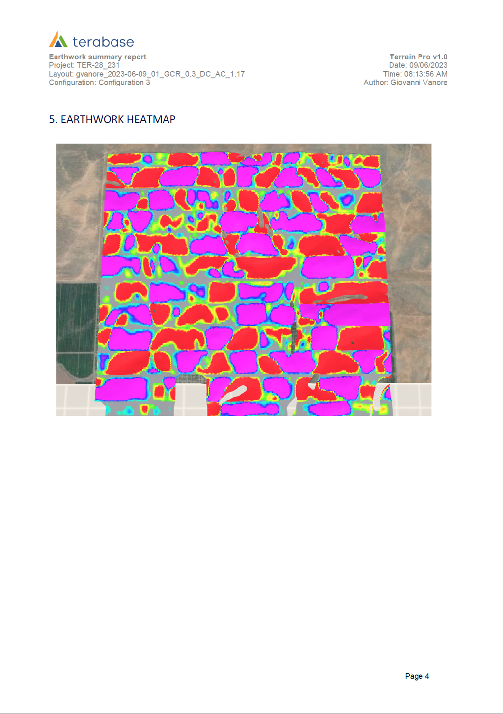
* A snapshot of the earthwork heat map.
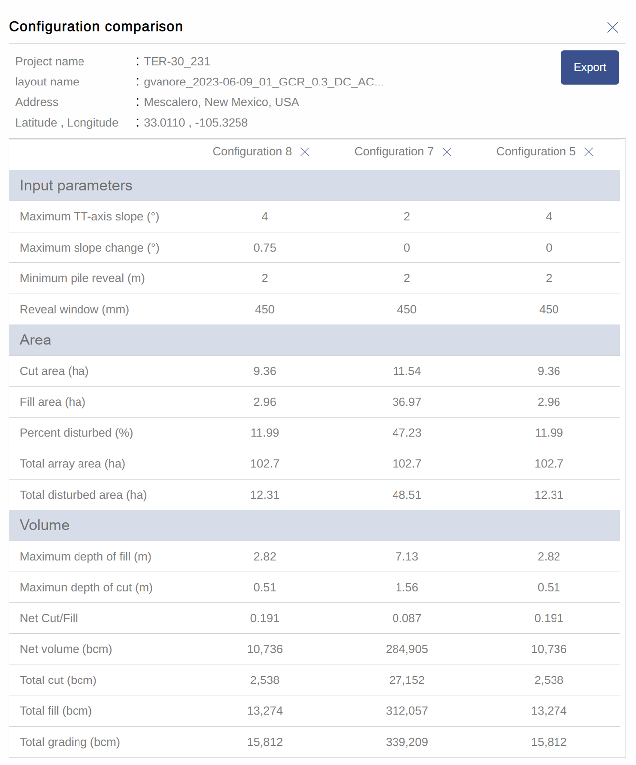
## **Terrain analysis comparison report**
The terrain analysis comparison report, allows the user to compare side by side up to four configurations created in Terrain Pro.
## **Terrain analysis report**
By clicking on the button “Generate report” an earthwork summary report for the configuration visualized on the screen is generated and downloaded on the user computer in pdf format.
The report includes:
* The input parameters.
* The coordinate system and the elevation source for the DP layout.
* The earthwork outputs.
* A snapshot of the earthwork heat map.
## **Terrain analysis comparison report**
The terrain analysis comparison report, allows the user to compare side by side up to four configurations created in Terrain Pro.
 ## **Download pile’s data**
Clicking on the **Download** button on the top right corner of the screen, the file’s data will be downloaded, in csv format, on the user's device.\
The data will include the following information for every pile:
* PileID
* Easting
* Northing
* Existing Grade
* Finish Grade
* Pile Reveal
* Top of Pile
## **Generate summary report**
Clicking on the **Generate report** button on the top right corner of the screen, the Terrain Pro will be generated and downloaded, in pdf format, on the user’s device.\
The report is generated on the fly, so few seconds are required to create a snapshot of the earthwork heatmap to be added to the last page of the report.
The generation of the report takes between 20 to 30 seconds, because the application is rendering the earthwork heat map in the back. please don’t perform other actions while generating the report.
## **Download pile’s data**
Clicking on the **Download** button on the top right corner of the screen, the file’s data will be downloaded, in csv format, on the user's device.\
The data will include the following information for every pile:
* PileID
* Easting
* Northing
* Existing Grade
* Finish Grade
* Pile Reveal
* Top of Pile
## **Generate summary report**
Clicking on the **Generate report** button on the top right corner of the screen, the Terrain Pro will be generated and downloaded, in pdf format, on the user’s device.\
The report is generated on the fly, so few seconds are required to create a snapshot of the earthwork heatmap to be added to the last page of the report.
The generation of the report takes between 20 to 30 seconds, because the application is rendering the earthwork heat map in the back. please don’t perform other actions while generating the report.
 ## **PVC file**
The PVC file available for every completed configuration can be used for shade analysis in PlantPredict 3D
## **Pile configurator**
The link to the pile configurator will open the Terrain Pro extension pushing the pile data from the configuration directly to the application, allowing the user to perform the pile binning and estimate the quantity of steel in the configuration - Click [here](https://terabase.atlassian.net/wiki/spaces/PPKB/pages/2031124482 "https://terabase.atlassian.net/wiki/spaces/PPKB/pages/2031124482") for the Pile configurator user guide.
## **Units**
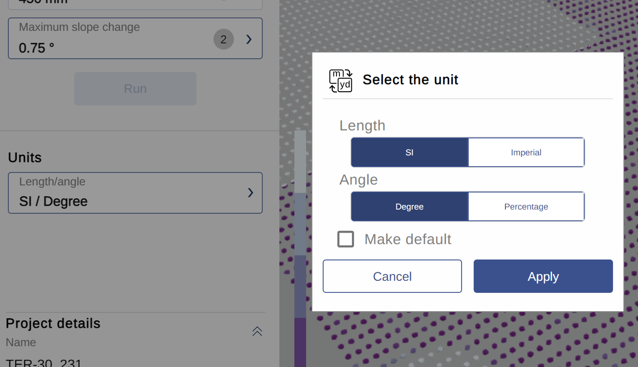
The units used on Terrain Pro for the length and the angle can be changed by opening the Unit container and selecting the preferred unit combination
## **PVC file**
The PVC file available for every completed configuration can be used for shade analysis in PlantPredict 3D
## **Pile configurator**
The link to the pile configurator will open the Terrain Pro extension pushing the pile data from the configuration directly to the application, allowing the user to perform the pile binning and estimate the quantity of steel in the configuration - Click [here](https://terabase.atlassian.net/wiki/spaces/PPKB/pages/2031124482 "https://terabase.atlassian.net/wiki/spaces/PPKB/pages/2031124482") for the Pile configurator user guide.
## **Units**
The units used on Terrain Pro for the length and the angle can be changed by opening the Unit container and selecting the preferred unit combination