> ## Documentation Index
> Fetch the complete documentation index at: https://docs.plantpredict.com/llms.txt
> Use this file to discover all available pages before exploring further.
# How to Model East/West Dual Tilt Systems
> Workflow for modeling East-West dual tilt PV systems in PlantPredict using 5B Maverick racking as an example
This page walks through how to design and model an **East-West dual tilt** PV system in PlantPredict. The example uses **5B Maverick** racking, but the same workflow applies to any East-West dual-tilt racking product.
The general approach is:
1. Lay out the site in [Power Plant Builder (On Map)](/user-guide/ui/power-plant-builder-map-interface) using **0° tilt** so the geometry fits the site boundary correctly.
2. Clone the prediction and convert it to [Power Plant Builder (By Block)](/user-guide/ui/power-plant-builder-block) to apply a slight East/West tilt and run an energy prediction that reflects the actual module orientation.
***
## Reference and Setup
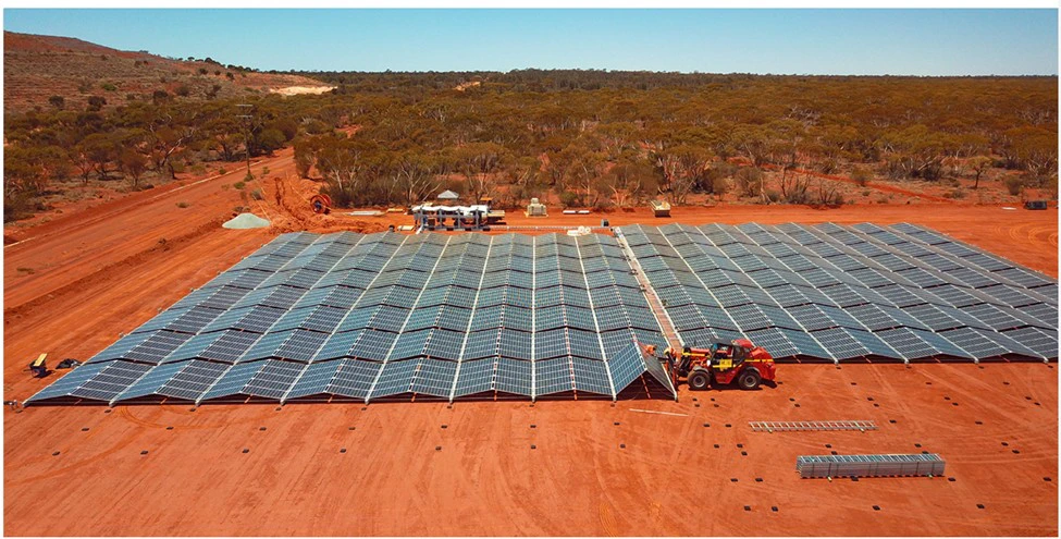
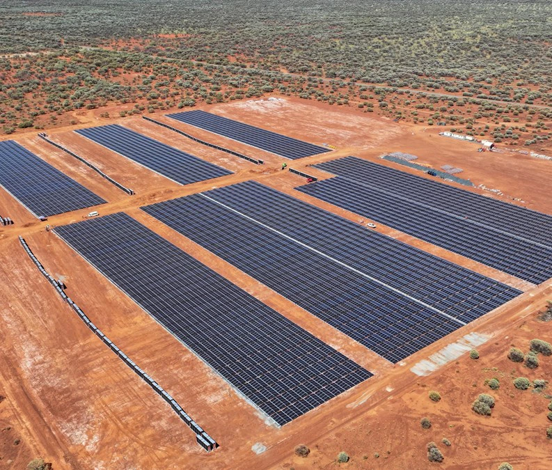
When designing an East-West dual tilt system, it helps to have a datasheet from your racking provider so you know how the table spacing works and what the dimensions of the table are.
This example uses the **5B Maverick** data sheet (available from [5B](https://5b.co/)). Two key points from the datasheet:
* East-West tables come in a **2 Modules High (E–W)** by **5 Modules Wide (N–S)** configuration.
* There is a gap between the tables in the North–South direction of approximately **2 ft**.
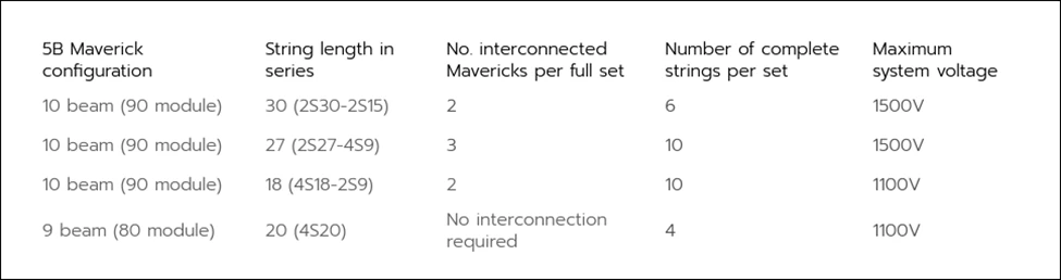
* The Maverick comes in either a **10 beam (90 module)** or a **9 beam (80 module)** configuration. This example uses the **10 beam (90 module)**, **30 module string length** configuration.
 ***
## Step 1 — Create the Layout in MapBuilder
With the racking parameters in mind, start by creating a **Project** and a **MapBuilder ("Build on the Map") Prediction**.
Open the [PV Blocks & Arrays](/user-guide/ui/power-plant-builder-map-interface) section of the prediction and define the site boundary. The example site shown below is located in Ohio.
***
## Step 1 — Create the Layout in MapBuilder
With the racking parameters in mind, start by creating a **Project** and a **MapBuilder ("Build on the Map") Prediction**.
Open the [PV Blocks & Arrays](/user-guide/ui/power-plant-builder-map-interface) section of the prediction and define the site boundary. The example site shown below is located in Ohio.
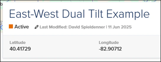 The site is **37.34 acres** and is approximately rectangular but slightly askew, so the azimuth will be adjusted later to align with the site boundaries.
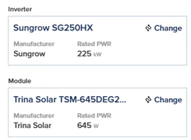
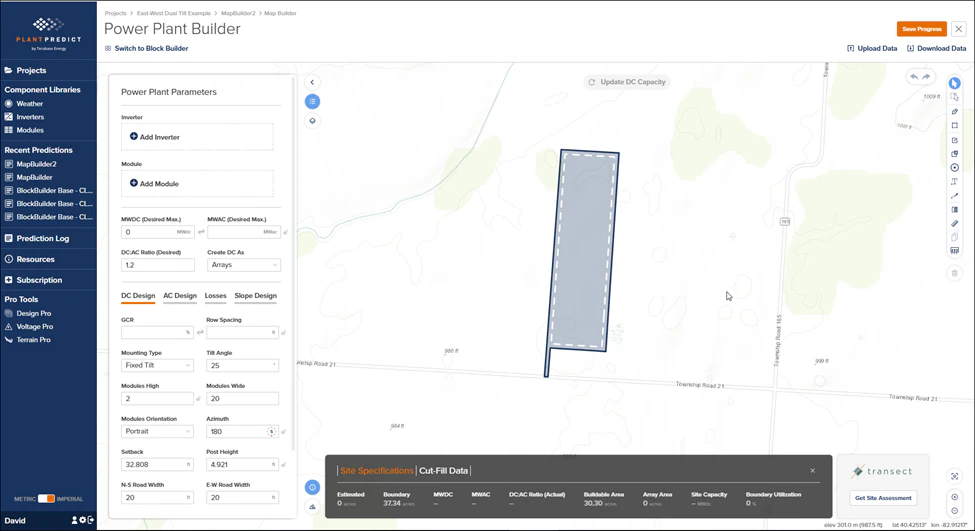 Select the inverter and module for the design:
* **Inverter**: Sungrow SG250HX string inverter
* **Module**: Trina TSM-645DEG21C.20
Select the inverter and module for the design:
* **Inverter**: Sungrow SG250HX string inverter
* **Module**: Trina TSM-645DEG21C.20
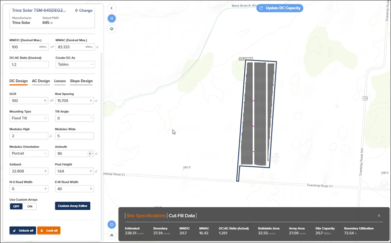
 With a **Desired DC Input** of **100 MWDC** (this site won't fit 100 MWDC, but we want to max it out), set the following:
| Parameter | Value |
| ----------------- | ---------- |
| Create DC as | **Tables** |
| GCR | **100 %** |
| Tilt Angle | **0°** |
| Modules High | **2** |
| Modules Wide | **5** |
| Azimuth | **90°** |
| North–South Roads | **0 ft** |
| East–West Roads | **40 ft** |
Setting **Tilt Angle = 0°** is intentional. The modules will have a slight tilt in reality, but using 0° here produces the correct table footprint for laying out the site.
The road settings look counterintuitive: we actually want **North–South** access roads. However, because the array is rotated 90° by the azimuth setting, the **East–West roads** in the form will run **North–South** on the ground.
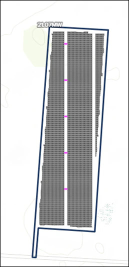
Click **Update DC Capacity**. The layout should look like the screenshot below.
With a **Desired DC Input** of **100 MWDC** (this site won't fit 100 MWDC, but we want to max it out), set the following:
| Parameter | Value |
| ----------------- | ---------- |
| Create DC as | **Tables** |
| GCR | **100 %** |
| Tilt Angle | **0°** |
| Modules High | **2** |
| Modules Wide | **5** |
| Azimuth | **90°** |
| North–South Roads | **0 ft** |
| East–West Roads | **40 ft** |
Setting **Tilt Angle = 0°** is intentional. The modules will have a slight tilt in reality, but using 0° here produces the correct table footprint for laying out the site.
The road settings look counterintuitive: we actually want **North–South** access roads. However, because the array is rotated 90° by the azimuth setting, the **East–West roads** in the form will run **North–South** on the ground.
Click **Update DC Capacity**. The layout should look like the screenshot below.
 ***
## Step 2 — Tweak the Layout with the Custom Array Editor
The initial layout looks good but needs some minor tweaks.
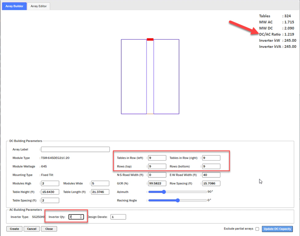
Flip the **Use Custom Arrays** switch to **On**. This opens the [Custom Array Editor](/user-guide/ui/power-plant-builder-custom-array-editor).
Update the following values in the Custom Array Editor:
* **Tables in Row (Left)** = **9**
* **Tables in Row (Right)** = **9**
* **Rows (Top)** = **9**
* **Rows (Bottom)** = **9**
Then adjust the **Inverter Quantity** to achieve your target **DC/AC Ratio**. In this example, **Inverter Qty = 7** gives a DC/AC ratio as close to **1.20** as possible.
***
## Step 2 — Tweak the Layout with the Custom Array Editor
The initial layout looks good but needs some minor tweaks.
Flip the **Use Custom Arrays** switch to **On**. This opens the [Custom Array Editor](/user-guide/ui/power-plant-builder-custom-array-editor).
Update the following values in the Custom Array Editor:
* **Tables in Row (Left)** = **9**
* **Tables in Row (Right)** = **9**
* **Rows (Top)** = **9**
* **Rows (Bottom)** = **9**
Then adjust the **Inverter Quantity** to achieve your target **DC/AC Ratio**. In this example, **Inverter Qty = 7** gives a DC/AC ratio as close to **1.20** as possible.
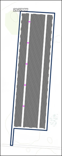
 Click **Update DC Capacity** again.
 Because the site is slightly askew, adjust the **Azimuth** to make the roads and tables align with the site boundary.
* In the Custom Array Editor, set **Azimuth = 94°**.
* Click **Update DC Capacity**.
Because the site is slightly askew, adjust the **Azimuth** to make the roads and tables align with the site boundary.
* In the Custom Array Editor, set **Azimuth = 94°**.
* Click **Update DC Capacity**.
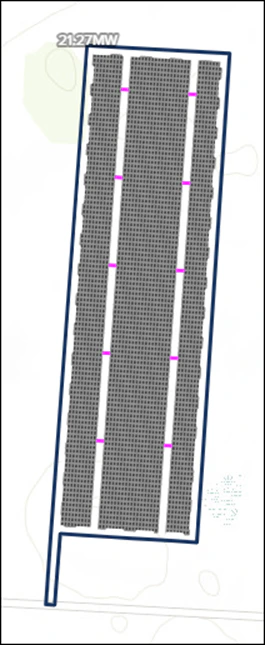
 For aesthetic purposes, you can duplicate the Power Conversion Stations that are in the **western access road** and place them in the **eastern access road**.
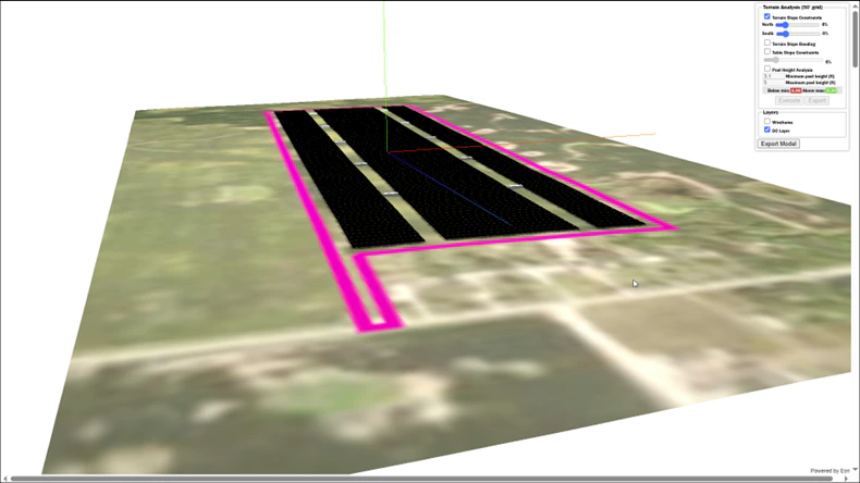
 Click the [**3D View**](/user-guide/ui/power-plant-builder-3d-view) link to see the full site from a 3D perspective and compare with the images in the racking datasheet.
 ***
## Step 3 — Run an Energy Prediction in Block Builder
You can use the **MapBuilder design with 0° tilt** to get a rough estimate of energy production. However, most East-West sites will have a slight East and West tilt, which increases overall energy production. To capture this, clone the MapBuilder prediction and convert it to a [Block Builder prediction](/user-guide/ui/power-plant-builder-block).
1. **Clone** your MapBuilder prediction.
2. Rename the cloned prediction so it is clear it is going to be a Block Builder prediction with a slight module slope.
3. Open **PV Blocks & Arrays** and click the **Convert to Block Builder** button.
Once you convert a MapBuilder prediction to a Block Builder prediction, **there is no going back**. You can never recover the MapBuilder layout. That is why we recommend cloning first.
**GCR note:** The MapBuilder layout uses **GCR = 100 %** for layout generation. After converting to Block Builder and splitting the system into East-facing and West-facing DC Fields, set the **GCR to 50 %** for both DC Fields. Because the East and West sides are modeled separately in Block Builder, each field represents one side of the East-West table arrangement.
In the **Electrical Configuration** of the power plant, note the **MWdc of the DC Field(s)** and divide that number in half. You will create two DC Fields:
* One for the **East-facing racks**
* One for the **West-facing racks**
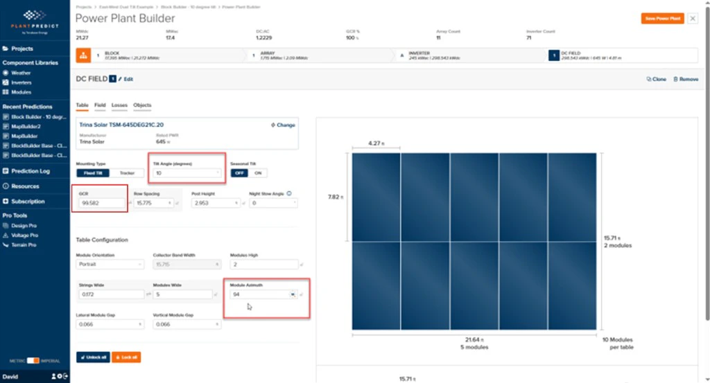
On the **Table** tab of the East-facing DC Field, set:
* **Tilt Angle = 10°**
* **Azimuth = 94°**
* **GCR = 50 %**
***
## Step 3 — Run an Energy Prediction in Block Builder
You can use the **MapBuilder design with 0° tilt** to get a rough estimate of energy production. However, most East-West sites will have a slight East and West tilt, which increases overall energy production. To capture this, clone the MapBuilder prediction and convert it to a [Block Builder prediction](/user-guide/ui/power-plant-builder-block).
1. **Clone** your MapBuilder prediction.
2. Rename the cloned prediction so it is clear it is going to be a Block Builder prediction with a slight module slope.
3. Open **PV Blocks & Arrays** and click the **Convert to Block Builder** button.
Once you convert a MapBuilder prediction to a Block Builder prediction, **there is no going back**. You can never recover the MapBuilder layout. That is why we recommend cloning first.
**GCR note:** The MapBuilder layout uses **GCR = 100 %** for layout generation. After converting to Block Builder and splitting the system into East-facing and West-facing DC Fields, set the **GCR to 50 %** for both DC Fields. Because the East and West sides are modeled separately in Block Builder, each field represents one side of the East-West table arrangement.
In the **Electrical Configuration** of the power plant, note the **MWdc of the DC Field(s)** and divide that number in half. You will create two DC Fields:
* One for the **East-facing racks**
* One for the **West-facing racks**
On the **Table** tab of the East-facing DC Field, set:
* **Tilt Angle = 10°**
* **Azimuth = 94°**
* **GCR = 50 %**
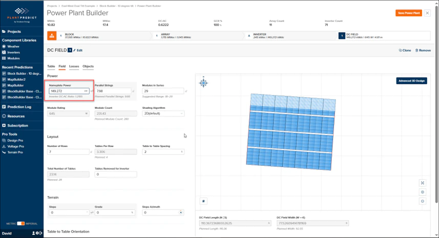
 Then click the **Field** tab and change the **Nameplate Power** to half of what is currently displayed (for example, if it started as 298.543 MW, change it to 149.272 MW).
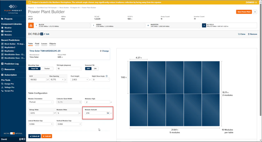
 Click the **Clone** link to create the second DC Field. The cloned field retains the **Tilt Angle = 10°** and **GCR = 50 %** inputs from the East-facing DC Field.
Set **Azimuth = 94° + 180° = 274°**.
Click the **Clone** link to create the second DC Field. The cloned field retains the **Tilt Angle = 10°** and **GCR = 50 %** inputs from the East-facing DC Field.
Set **Azimuth = 94° + 180° = 274°**.
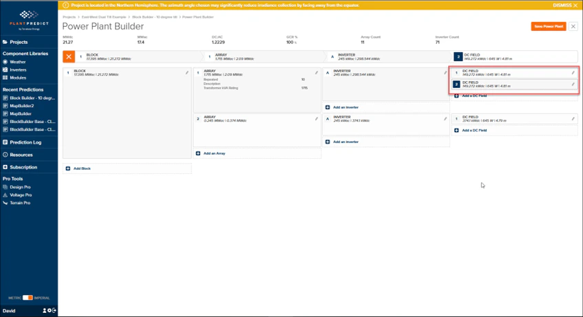
 Confirm that the **Nameplate Power** matches the East-facing DC Field and remains half of the original converted DC Field value.
Click the **Orange Org Chart** icon to view the Block Design. You should see **2 DC Fields connected to Inverter A in Array 1**. If there are more arrays in your design, repeat the same steps for each one.
Confirm that the **Nameplate Power** matches the East-facing DC Field and remains half of the original converted DC Field value.
Click the **Orange Org Chart** icon to view the Block Design. You should see **2 DC Fields connected to Inverter A in Array 1**. If there are more arrays in your design, repeat the same steps for each one.
 ***
## Step 4 — Run the Final Prediction
1. **Save** the Power Plant.
2. **Run the Prediction**.
3. Go back to the Project and use **Compare Multiple Results** to see the difference between:
* The **MapBuilder** prediction (0° tilt)
* The **Block Builder** prediction (10° East-West tilt)
Comparing the two predictions quantifies the energy gain from modeling the actual East/West tilt versus the simplified 0° layout used for site planning.
***
## Step 4 — Run the Final Prediction
1. **Save** the Power Plant.
2. **Run the Prediction**.
3. Go back to the Project and use **Compare Multiple Results** to see the difference between:
* The **MapBuilder** prediction (0° tilt)
* The **Block Builder** prediction (10° East-West tilt)
Comparing the two predictions quantifies the energy gain from modeling the actual East/West tilt versus the simplified 0° layout used for site planning.