> ## Documentation Index
> Fetch the complete documentation index at: https://docs.plantpredict.com/llms.txt
> Use this file to discover all available pages before exploring further.
# Inverter Operating Regions
export const MaximumPowerPoint = () =>
maximum power point
;
export const SingleDiodeModel = () =>
single-diode model
;
export const OpenCircuitVoltage = () =>
open-circuit voltage
;
export const Clipping = () =>
clipping
;
export const Inverter = () =>
inverter
;
## Summary
Inverter Operating Regions classify the operational state of the based on DC voltage and power relative to inverter specifications, and adjust the operating voltage and power accordingly. PlantPredict divides the voltage-power plane into 12 regions using three voltage thresholds ($V_{MPP,min}$, $V_{MPP,max}$, $V_{max}$) and two power thresholds ($P_{min}$, $P_{max}$). Region 6 represents normal MPPT operation. Other regions trigger specific control actions: voltage adjustment (regions 5, 7, 9, 11), (region 10), or shutdown (regions 1-4, 8, 12).
## Inputs
| Name | Symbol | Units | Description |
| ----------------------------------- | ---------------- | ----- | ----------------------------------------------------------------------------------- |
| **DC Operating Voltage** | $V_{DC}$ | V | DC operating voltage from [DC field aggregation](dc_field_aggregation) |
| **DC Operating Power** | $P_{DC}$ | W | DC operating power from [DC field aggregation](dc_field_aggregation) |
| **Degraded DC Power** | $P_{DC,deg}$ | W | DC operating power after [degradation](degradation_dc_applied) |
| **DC Degradation Loss** | $L_{deg}$ | W | DC power loss due to [degradation](degradation_dc_applied) |
| **Minimum MPP Voltage** | $V_{MPP,min}$ | V | Inverter lower MPP tracking voltage limit |
| **Maximum MPP Voltage** | $V_{MPP,max}$ | V | Inverter upper MPP tracking voltage limit |
| **Maximum Absolute Voltage** | $V_{max}$ | V | Inverter absolute voltage limit |
| **Minimum DC Power** | $P_{min}$ | W | Inverter low-power cutoff threshold |
| **Temperature-Corrected Max Power** | $P_{AC,derated}$ | W | Inverter AC power limit after [temperature derating](inverter_temperature_derating) |
| **MPP Voltage Adjustment** | $\Delta V_{MPP}$ | % | User-defined time-series adjustment factor for voltage |
| **MPP Current Adjustment** | $\Delta I_{MPP}$ | % | User-defined time-series adjustment factor for current |
| **DC Open-Circuit Voltage** | $V_{DC,oc}$ | V | Aggregated open-circuit voltage from [DC field aggregation](dc_field_aggregation) |
***
## Outputs
| Name | Symbol | Units | Description |
| ------------------------ | -------- | ----- | --------------------------------------------------------------- |
| **DC Operating Voltage** | $V_{DC}$ | V | DC operating voltage after region-based adjustment (reassigned) |
| **DC Operating Power** | $P_{DC}$ | W | DC operating power after region-based adjustment (reassigned) |
***
## Detailed Description
This model receives $V_{DC}$ and $P_{DC,deg}$ from upstream ([DC field aggregation](dc_field_aggregation) and [degradation](degradation_dc_applied)). When the operating region requires an adjustment (voltage shift, clipping, or shutdown), $V_{DC}$ and $P_{DC}$ are reassigned in place using the $\leftarrow$ notation. In normal MPPT operation (region 6), $V_{DC}$ is unchanged and $P_{DC} \leftarrow P_{DC,deg}$.
### Voltage and Power Thresholds
The three voltage thresholds ($V_{MPP,min}$, $V_{MPP,max}$, $V_{max}$) and the low-power threshold ($P_{min}$) are taken directly from the inverter specifications. The upper power threshold $P_{max}$ is the DC equivalent of the derated AC power limit, where $\eta$ is the [inverter DC-to-AC conversion efficiency](inverter_efficiency) evaluated at the operating voltage $V_{DC}$ and the derated AC power $P_{AC,derated}$:
$$
P_{max} = \frac{P_{AC,derated}}{\eta(V_{DC},\, P_{AC,derated})}
$$
This is a preliminary evaluation of the efficiency model at a known operating point; the [Inverter Efficiency](inverter_efficiency) model runs again after operating-region adjustments to produce the final $\eta$ and $P_{AC,inv}$.
### Threshold Adjustment via Time Series
When user-defined $V_{MPP}$ and $I_{MPP}$ time-series adjustments are provided, the voltage and power thresholds are reassigned at each timestep to account for expected deviations from nameplate conditions:
$$
V_{MPP,min} \leftarrow \frac{V_{MPP,min}}{1 + \Delta V_{MPP}}
$$
$$
V_{MPP,max} \leftarrow \frac{V_{MPP,max}}{1 + \Delta V_{MPP}}
$$
$$
V_{max} \leftarrow \frac{V_{max}}{1 + \Delta V_{MPP}}
$$
$$
P_{min} \leftarrow \frac{P_{min}}{(1 + \Delta I_{MPP})(1 + \Delta V_{MPP})}
$$
$$
P_{max} \leftarrow \frac{P_{max}}{(1 + \Delta I_{MPP})(1 + \Delta V_{MPP})}
$$
If no time-series adjustments are defined, $\Delta V_{MPP} = 0$ and $\Delta I_{MPP} = 0$, and the thresholds remain at their base values.
### Region Definitions
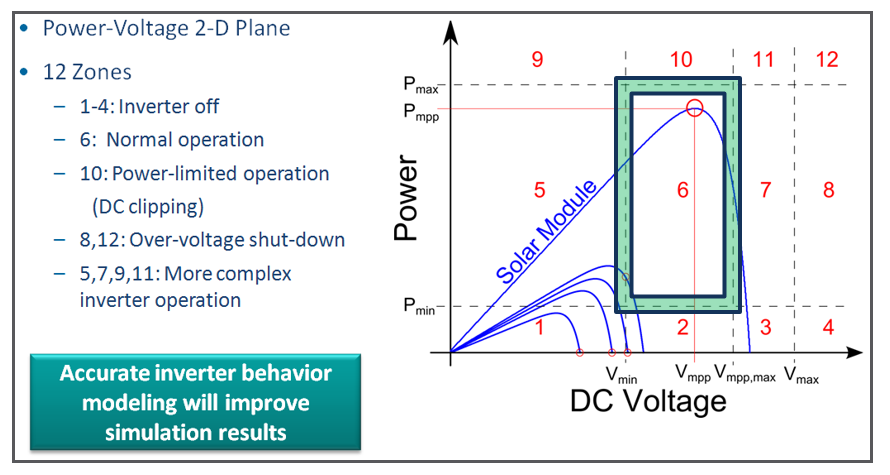 Given the operating point $(V, P) = (V_{DC}, P_{DC,deg})$, the operating region is determined by the following rules:
**Region 1:** $P \leq P_{min}$ and $V \leq V_{MPP,min}$ (Under-voltage, under-power)
**Region 2:** $P \leq P_{min}$ and $V_{MPP,min} \leq V \leq V_{MPP,max}$ (Under-power, normal voltage)
**Region 3:** $P \leq P_{min}$ and $V_{MPP,max} \leq V \leq V_{max}$ (Under-power, over-voltage)
**Region 4:** $P \leq P_{min}$ and $V \geq V_{max}$ (Under-power, severe over-voltage)
**Region 5:** $P_{min} \leq P \leq P_{max}$ and $V \leq V_{MPP,min}$ (Under-voltage)
**Region 6:** $P_{min} \leq P \leq P_{max}$ and $V_{MPP,min} \leq V \leq V_{MPP,max}$ (**Normal MPPT operation**)
**Region 7:** $P_{min} \leq P \leq P_{max}$ and $V_{MPP,max} \leq V \leq V_{max}$ (Over-voltage)
**Region 8:** $P_{min} \leq P \leq P_{max}$ and $V \geq V_{max}$ (Severe over-voltage)
**Region 9:** $P \geq P_{max}$ and $V \leq V_{MPP,min}$ (Clipping, under-voltage)
**Region 10:** $P \geq P_{max}$ and $V_{MPP,min} \leq V \leq V_{MPP,max}$ (Clipping, normal voltage)
**Region 11:** $P \geq P_{max}$ and $V_{MPP,max} \leq V \leq V_{max}$ (Clipping, over-voltage)
**Region 12:** $P \geq P_{max}$ and $V \geq V_{max}$ (Clipping, severe over-voltage)
All boundaries use inclusive comparisons ($\leq$, $\geq$), so a point lying exactly on a threshold can satisfy multiple region conditions simultaneously. See [Boundary Overlap and Tie-Breaking](#boundary-overlap-and-tie-breaking) for how ambiguities are resolved.
### Boundary Overlap and Tie-Breaking
Because region boundaries are inclusive, an operating point that falls exactly on a threshold can match two or four regions at once. PlantPredict resolves these overlaps as follows:
1. **Single match** — use that region.
2. **Two matches** (edge of the grid, on one threshold):
* If region 6 is among the matches, assign region 6.
* If both regions are below 7, the higher-number region is selected (favoring the active-power region over shutdown, if applicable).
* If the pair is (9, 10): assign region 10 (clipping).
* Otherwise, the lower-number region is selected.
3. **Four matches** (corner of the grid, where two thresholds intersect):
* If region 6 is among the matches, assign region 6.
* Otherwise, use the lowest-number match.
The net effect is that boundary points are resolved in favor of normal MPPT operation when possible, and otherwise in favor of the less disruptive control action.
### Control Actions by Region
**Regions 1, 2, 3:** Set voltage to $V_{DC,oc}$ (shutdown)
**Regions 4, 8, 12:** Set voltage to 0 (safety shutdown)
**Regions 5, 9:** Increase voltage to $V_{MPP,min}$ (or $V_{DC,oc}$ if $V_{oc} < V_{MPP,min}$), recalculate region
**Region 6: Normal operation (MPPT tracking)**
**Regions 7, 11:** Decrease voltage to $V_{MPP,max}$, recalculate region
**Region 10:** Clipping algorithm—Find voltage where $P = P_{max}$
For voltage adjustment regions (5, 7, 9, 11) and clipping (region 10), the inverter is set to a new operating voltage. The power at that voltage is recalculated from the associated with each connected DC field, and the region is re-evaluated at the new operating point. Shutdown regions (1–4, 8, 12) set the voltage directly without recalculation.
In region 6 (normal MPPT), no adjustment is made: $V_{DC}$ is unchanged and $P_{DC} \leftarrow P_{DC,deg}$. The initial and final operating region integers are both reported in the inverter nodal data.
When nighttime disconnect is enabled, the operating region is also used to determine whether the array's transformers should be disconnected from the grid. Disconnect is triggered when any inverter in the array enters a shutdown region (regions 1–4), region 5 with zero power, or region 6 with GHI \< 5 W/m². See [Transformer Loss Model](../ac-losses/transformer_loss_model) for downstream effects.
### Clipping Algorithm (Region 10)
When the operating point falls in Region 10 (over-power), the inverter cannot operate at the because doing so would exceed its AC power capacity. The algorithm must find a new voltage $V_{clip}$ on the P-V curve where the DC power is within the inverter's limits, as close to $P_{max}$ as possible.
Starting from $V_{DC,oc}$, the algorithm sweeps downward along the P-V curve, recalculating total DC power from all connected DC fields at each candidate voltage using their respective single-diode models. The selected $V_{clip}$ is the voltage at or below $V_{MPP,max}$ with power closest to $P_{max}$.
In V6 and earlier, $V_{clip}$ is accepted as is. In V7 and later, $P_{max}$ is recalculated at the clipped operating point (since $\eta$ depends on both voltage and power) and the region is re-evaluated:
* **Region 6**: the clipped point is within normal MPPT limits—clipping is successful.
* **Region 10, but within 0.1% of the recalculated $P_{max}$**: the operating point is accepted and the region is reassigned to region 6—clipping is successful.
* **Otherwise**: no valid clipping point can be found, the inverter shuts down (Region 1, $V_{DC,oc}$ shutdown).
### Loss Tree Reporting
The loss tree reports an "Off-MPP Power Loss" at the inverter level. This loss captures the combined effect of all inverter-level DC power adjustments after degradation—including clipping, voltage adjustment, and shutdown:
$$
L_{off-MPP} = P_{DC,deg} - P_{DC}
$$
In normal MPPT operation (region 6), $P_{DC} \leftarrow P_{DC,deg}$ and the off-MPP loss is zero. The loss becomes nonzero when the inverter operating region forces the system away from the aggregated maximum power point—most commonly during clipping (region 10), where excess DC power is curtailed to the inverter's rated capacity.
Note that $L_{deg}$ is not recalculated at the adjusted operating point. During clipping, the output power matches $P_{max}$ regardless, so the total power is correct—but since degradation loss is proportional to power and the clipped power is lower, $L_{deg}$ is slightly overestimated and $L_{off-MPP}$ is slightly underestimated by the same amount. During voltage adjustment (regions 5, 7, 9, 11), the pre-degradation power decreases but $L_{deg}$ remains unchanged, leading to a slight overestimation of losses and underestimation of output power.
Given the operating point $(V, P) = (V_{DC}, P_{DC,deg})$, the operating region is determined by the following rules:
**Region 1:** $P \leq P_{min}$ and $V \leq V_{MPP,min}$ (Under-voltage, under-power)
**Region 2:** $P \leq P_{min}$ and $V_{MPP,min} \leq V \leq V_{MPP,max}$ (Under-power, normal voltage)
**Region 3:** $P \leq P_{min}$ and $V_{MPP,max} \leq V \leq V_{max}$ (Under-power, over-voltage)
**Region 4:** $P \leq P_{min}$ and $V \geq V_{max}$ (Under-power, severe over-voltage)
**Region 5:** $P_{min} \leq P \leq P_{max}$ and $V \leq V_{MPP,min}$ (Under-voltage)
**Region 6:** $P_{min} \leq P \leq P_{max}$ and $V_{MPP,min} \leq V \leq V_{MPP,max}$ (**Normal MPPT operation**)
**Region 7:** $P_{min} \leq P \leq P_{max}$ and $V_{MPP,max} \leq V \leq V_{max}$ (Over-voltage)
**Region 8:** $P_{min} \leq P \leq P_{max}$ and $V \geq V_{max}$ (Severe over-voltage)
**Region 9:** $P \geq P_{max}$ and $V \leq V_{MPP,min}$ (Clipping, under-voltage)
**Region 10:** $P \geq P_{max}$ and $V_{MPP,min} \leq V \leq V_{MPP,max}$ (Clipping, normal voltage)
**Region 11:** $P \geq P_{max}$ and $V_{MPP,max} \leq V \leq V_{max}$ (Clipping, over-voltage)
**Region 12:** $P \geq P_{max}$ and $V \geq V_{max}$ (Clipping, severe over-voltage)
All boundaries use inclusive comparisons ($\leq$, $\geq$), so a point lying exactly on a threshold can satisfy multiple region conditions simultaneously. See [Boundary Overlap and Tie-Breaking](#boundary-overlap-and-tie-breaking) for how ambiguities are resolved.
### Boundary Overlap and Tie-Breaking
Because region boundaries are inclusive, an operating point that falls exactly on a threshold can match two or four regions at once. PlantPredict resolves these overlaps as follows:
1. **Single match** — use that region.
2. **Two matches** (edge of the grid, on one threshold):
* If region 6 is among the matches, assign region 6.
* If both regions are below 7, the higher-number region is selected (favoring the active-power region over shutdown, if applicable).
* If the pair is (9, 10): assign region 10 (clipping).
* Otherwise, the lower-number region is selected.
3. **Four matches** (corner of the grid, where two thresholds intersect):
* If region 6 is among the matches, assign region 6.
* Otherwise, use the lowest-number match.
The net effect is that boundary points are resolved in favor of normal MPPT operation when possible, and otherwise in favor of the less disruptive control action.
### Control Actions by Region
**Regions 1, 2, 3:** Set voltage to $V_{DC,oc}$ (shutdown)
**Regions 4, 8, 12:** Set voltage to 0 (safety shutdown)
**Regions 5, 9:** Increase voltage to $V_{MPP,min}$ (or $V_{DC,oc}$ if $V_{oc} < V_{MPP,min}$), recalculate region
**Region 6: Normal operation (MPPT tracking)**
**Regions 7, 11:** Decrease voltage to $V_{MPP,max}$, recalculate region
**Region 10:** Clipping algorithm—Find voltage where $P = P_{max}$
For voltage adjustment regions (5, 7, 9, 11) and clipping (region 10), the inverter is set to a new operating voltage. The power at that voltage is recalculated from the associated with each connected DC field, and the region is re-evaluated at the new operating point. Shutdown regions (1–4, 8, 12) set the voltage directly without recalculation.
In region 6 (normal MPPT), no adjustment is made: $V_{DC}$ is unchanged and $P_{DC} \leftarrow P_{DC,deg}$. The initial and final operating region integers are both reported in the inverter nodal data.
When nighttime disconnect is enabled, the operating region is also used to determine whether the array's transformers should be disconnected from the grid. Disconnect is triggered when any inverter in the array enters a shutdown region (regions 1–4), region 5 with zero power, or region 6 with GHI \< 5 W/m². See [Transformer Loss Model](../ac-losses/transformer_loss_model) for downstream effects.
### Clipping Algorithm (Region 10)
When the operating point falls in Region 10 (over-power), the inverter cannot operate at the because doing so would exceed its AC power capacity. The algorithm must find a new voltage $V_{clip}$ on the P-V curve where the DC power is within the inverter's limits, as close to $P_{max}$ as possible.
Starting from $V_{DC,oc}$, the algorithm sweeps downward along the P-V curve, recalculating total DC power from all connected DC fields at each candidate voltage using their respective single-diode models. The selected $V_{clip}$ is the voltage at or below $V_{MPP,max}$ with power closest to $P_{max}$.
In V6 and earlier, $V_{clip}$ is accepted as is. In V7 and later, $P_{max}$ is recalculated at the clipped operating point (since $\eta$ depends on both voltage and power) and the region is re-evaluated:
* **Region 6**: the clipped point is within normal MPPT limits—clipping is successful.
* **Region 10, but within 0.1% of the recalculated $P_{max}$**: the operating point is accepted and the region is reassigned to region 6—clipping is successful.
* **Otherwise**: no valid clipping point can be found, the inverter shuts down (Region 1, $V_{DC,oc}$ shutdown).
### Loss Tree Reporting
The loss tree reports an "Off-MPP Power Loss" at the inverter level. This loss captures the combined effect of all inverter-level DC power adjustments after degradation—including clipping, voltage adjustment, and shutdown:
$$
L_{off-MPP} = P_{DC,deg} - P_{DC}
$$
In normal MPPT operation (region 6), $P_{DC} \leftarrow P_{DC,deg}$ and the off-MPP loss is zero. The loss becomes nonzero when the inverter operating region forces the system away from the aggregated maximum power point—most commonly during clipping (region 10), where excess DC power is curtailed to the inverter's rated capacity.
Note that $L_{deg}$ is not recalculated at the adjusted operating point. During clipping, the output power matches $P_{max}$ regardless, so the total power is correct—but since degradation loss is proportional to power and the clipped power is lower, $L_{deg}$ is slightly overestimated and $L_{off-MPP}$ is slightly underestimated by the same amount. During voltage adjustment (regions 5, 7, 9, 11), the pre-degradation power decreases but $L_{deg}$ remains unchanged, leading to a slight overestimation of losses and underestimation of output power.