> ## Documentation Index
> Fetch the complete documentation index at: https://docs.plantpredict.com/llms.txt
> Use this file to discover all available pages before exploring further.
# Energy Storage Overview
export const SOC = () =>
SOC
;
export const RoundTripEfficiency = () =>
round-trip DC efficiency
;
export const LGIA = () =>
LGIA
;
export const Transformer = () =>
transformer
;
export const HV = () =>
HV
;
export const MV = () =>
MV
;
export const POI = () =>
POI
;
PlantPredict models AC-coupled battery energy storage systems (BESS) integrated with solar PV plants. The storage system connects at the bus through its own inverter and MV , sharing the plant's equipment and grid connection with the PV system. The ESS model determines when and how much the battery charges or discharges, tracks battery state over time, and combines the storage power flow with PV output to produce the final plant delivery at the .
## PV + ESS Prediction Flow
The full PV pipeline (irradiance, photovoltaic conversion, DC–AC conversion, array-level and block-level aggregation) runs once per timestep. The ESS calculation then runs using the PV results, and only the [plant-level power flow](/models/ac-losses/plant_level_losses) (HV equipment, availability, limit) is re-run with the combined output:
1. **PV pipeline** — Runs once. Block power is aggregated, then the plant-level power flow applies HV transformer and transmission line losses, availability loss, and LGIA limit. This produces the PV transformer output and the PV-only output at the POI, both of which are retained as inputs to the ESS model.
2. **ESS calculation** — Using the PV MV transformer output and the PV-only output at the POI, the ESS model runs its full calculation sequence (constraints, dispatch, battery state, power flow) and produces a combined PV+ESS output at the MV level.
3. **Plant-level power flow re-run** — The combined output replaces the PV block sum at the MV level and the plant-level power flow runs again: HV transformer and transmission line losses, availability loss, and LGIA limit are re-applied to the combined output. This produces the final plant output at the POI. The rest of the PV pipeline is not re-run.
## Node Positions
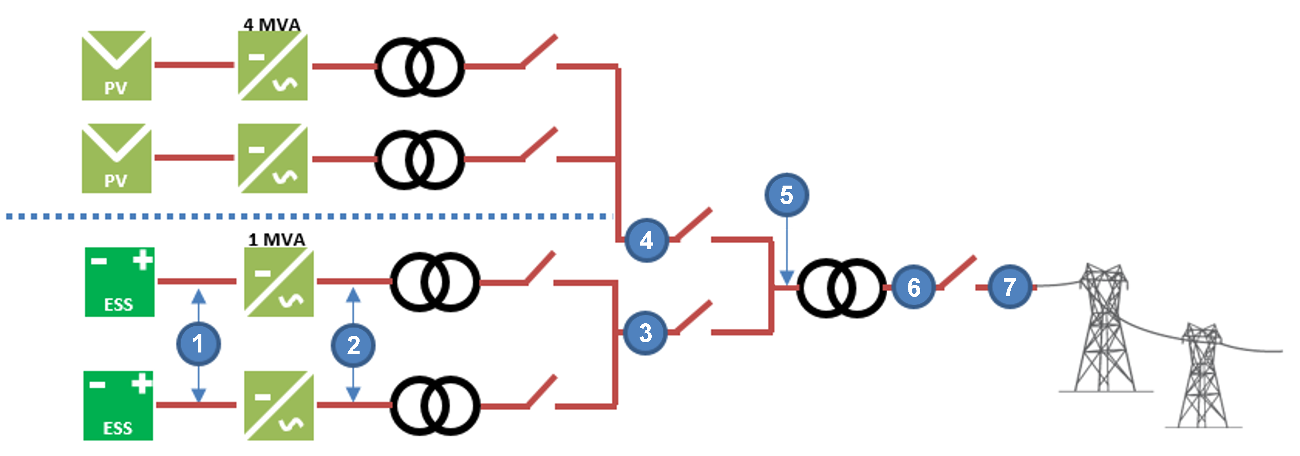 The energy storage model tracks power flow at seven node positions. These nodes represent measurement points where power values are calculated:
1. **Battery DC terminals** — DC power at the battery level
2. **Storage inverter AC output** — AC power after DC-AC conversion
3. **Storage MV transformer output** — Power from storage-side MV transformer
4. **PV MV transformer output** — Power from PV-system-side MV transformer
5. **Combined PV+ESS at MV** — Combined power from PV and storage systems
6. **HV equipment output** — Power after HV transformers and transmission lines
7. **Point of interconnection (POI)** — Final grid delivery point, after availability and LGIA adjustments
## Models in This Section
### [Charge & Discharge Limits](charge_discharge_limits)
Calculates the maximum power available for charging and discharging at each timestep.
**Charge limits:**
* PV excess above interconnect limit (LGIA Excess algorithm)
* Available PV power after storage MV transformer losses (Energy Available algorithm)
* Storage inverter capacity and efficiency
**Discharge limits:**
* LGIA headroom (remaining capacity below the interconnect limit)
* Storage inverter capacity
* MV transformer and HV equipment losses between battery and POI
### [Dispatch Algorithms](dispatch_algorithms)
Determines when the battery charges and discharges by setting intent flags for each timestep. Three algorithms are available:
* **LGIA Excess**: charges when PV output exceeds interconnect capacity
* **Energy Available**: charges when PV energy is available and not in discharge period
* **Custom Dispatch**: user-defined charge/discharge schedule
### [Battery Model](battery_model)
Tracks the battery's internal state and derives the resulting power flows:
* **Degradation**: capacity and decline from cycling and aging (additive)
* **State of charge**: updates the energy stored in the battery, based on three independent factors—the dispatch flags (charge, discharge, or idle), the power limits (hardware and grid constraints), and the current (clamped between full and empty)
* **DC and AC power**: derived from the actual SOC change—zero when idle, and potentially lower than the power limits if the battery is full or empty
### [Power Flow to Grid](power_flow)
Transforms battery AC power into grid-deliverable output:
1. Storage MV transformer losses (charge, discharge, and no-load loss when idle)
2. Combined PV+ESS output at MV (PV output adjusted for battery charging or discharging)
3. Plant-level power flow re-run: HV equipment losses, availability loss, LGIA limit
## Calculation Sequence
1. Calculate available charge and discharge power ([Charge & Discharge Limits](charge_discharge_limits))
2. Set charge/discharge intent flags from [Dispatch Algorithms](dispatch_algorithms)
3. Update degradation, then state of charge, then calculate DC and AC power ([Battery Model](battery_model))
4. Apply storage MV transformer losses ([Power Flow to Grid](power_flow))
5. Combine PV and storage at MV, adjusting PV output for battery charging/discharging ([Power Flow to Grid](power_flow))
6. Re-run plant-level power flow with combined output (HV equipment, availability, LGIA limit)
The energy storage model tracks power flow at seven node positions. These nodes represent measurement points where power values are calculated:
1. **Battery DC terminals** — DC power at the battery level
2. **Storage inverter AC output** — AC power after DC-AC conversion
3. **Storage MV transformer output** — Power from storage-side MV transformer
4. **PV MV transformer output** — Power from PV-system-side MV transformer
5. **Combined PV+ESS at MV** — Combined power from PV and storage systems
6. **HV equipment output** — Power after HV transformers and transmission lines
7. **Point of interconnection (POI)** — Final grid delivery point, after availability and LGIA adjustments
## Models in This Section
### [Charge & Discharge Limits](charge_discharge_limits)
Calculates the maximum power available for charging and discharging at each timestep.
**Charge limits:**
* PV excess above interconnect limit (LGIA Excess algorithm)
* Available PV power after storage MV transformer losses (Energy Available algorithm)
* Storage inverter capacity and efficiency
**Discharge limits:**
* LGIA headroom (remaining capacity below the interconnect limit)
* Storage inverter capacity
* MV transformer and HV equipment losses between battery and POI
### [Dispatch Algorithms](dispatch_algorithms)
Determines when the battery charges and discharges by setting intent flags for each timestep. Three algorithms are available:
* **LGIA Excess**: charges when PV output exceeds interconnect capacity
* **Energy Available**: charges when PV energy is available and not in discharge period
* **Custom Dispatch**: user-defined charge/discharge schedule
### [Battery Model](battery_model)
Tracks the battery's internal state and derives the resulting power flows:
* **Degradation**: capacity and decline from cycling and aging (additive)
* **State of charge**: updates the energy stored in the battery, based on three independent factors—the dispatch flags (charge, discharge, or idle), the power limits (hardware and grid constraints), and the current (clamped between full and empty)
* **DC and AC power**: derived from the actual SOC change—zero when idle, and potentially lower than the power limits if the battery is full or empty
### [Power Flow to Grid](power_flow)
Transforms battery AC power into grid-deliverable output:
1. Storage MV transformer losses (charge, discharge, and no-load loss when idle)
2. Combined PV+ESS output at MV (PV output adjusted for battery charging or discharging)
3. Plant-level power flow re-run: HV equipment losses, availability loss, LGIA limit
## Calculation Sequence
1. Calculate available charge and discharge power ([Charge & Discharge Limits](charge_discharge_limits))
2. Set charge/discharge intent flags from [Dispatch Algorithms](dispatch_algorithms)
3. Update degradation, then state of charge, then calculate DC and AC power ([Battery Model](battery_model))
4. Apply storage MV transformer losses ([Power Flow to Grid](power_flow))
5. Combine PV and storage at MV, adjusting PV output for battery charging/discharging ([Power Flow to Grid](power_flow))
6. Re-run plant-level power flow with combined output (HV equipment, availability, LGIA limit)